 .
.A
B
C
D
Text Solution
Verified by Experts
The correct Answer is:


Topper's Solved these Questions
SEMI CONDUCTOR DEVICES
NARAYNA|Exercise Level-I (C.W)|21 VideosSEMI CONDUCTOR DEVICES
NARAYNA|Exercise Level-II (C.W)|33 VideosSEMI CONDUCTOR DEVICES
NARAYNA|Exercise Level-II (H.W)|36 VideosRAY OPTICS AND OPTICAL INSTRAUMENTS
NARAYNA|Exercise EXERCISE- 4 One or more than one correct answer type|13 VideosSEMICONDUCTOR ELECTRONICS
NARAYNA|Exercise ADDITIONAL EXERCISE (ASSERTION AND REASON TYPE QUESTIONS :)|19 Videos
Similar Questions
Explore conceptually related problems
NARAYNA-SEMI CONDUCTOR DEVICES-C.U.Q
- Diffusion current in a p-n junction is greater than the drift current ...
Text Solution
|
- Germanium diode.
Text Solution
|
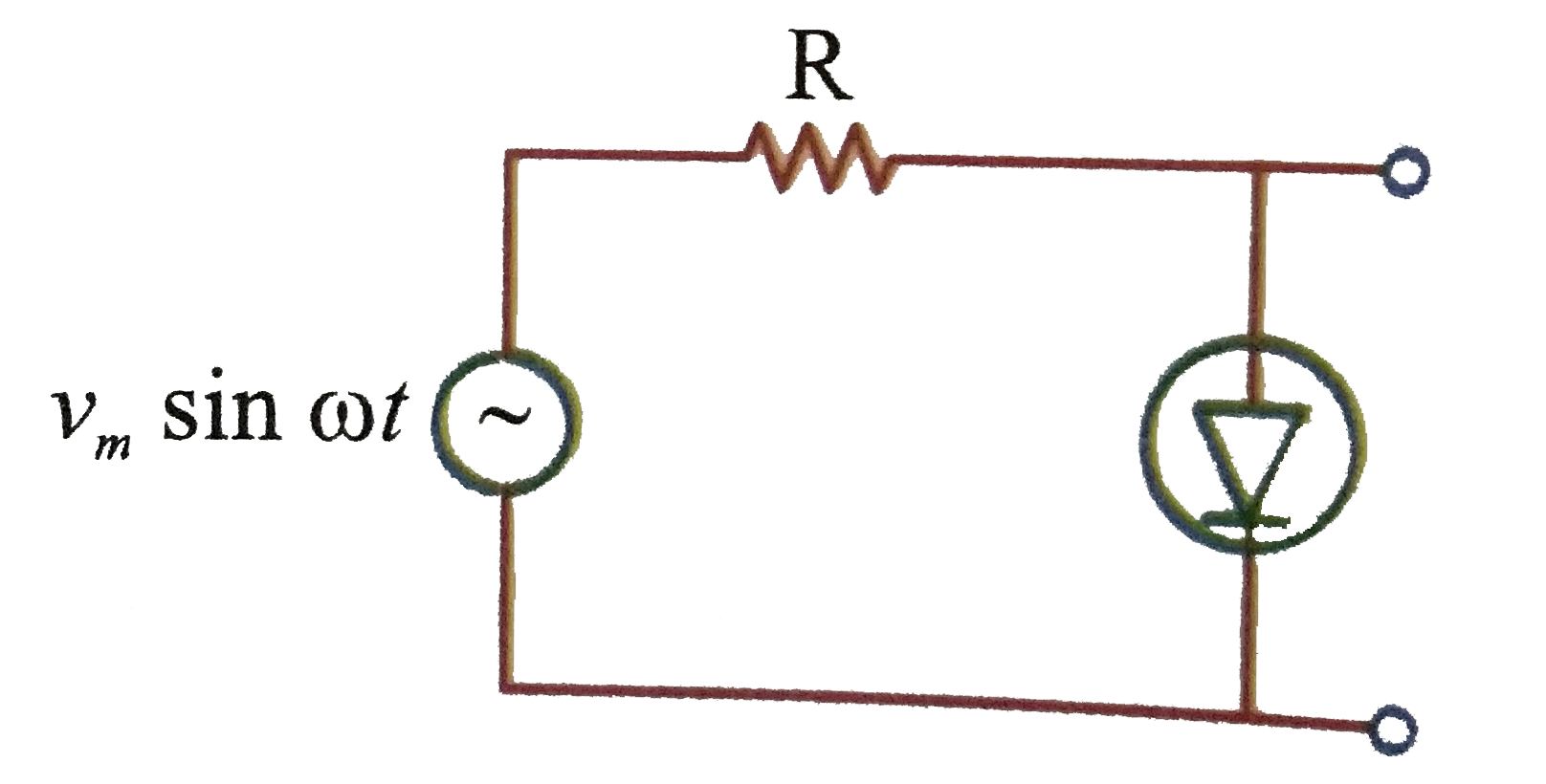
- The output of the given circuit in Fig. .
Text Solution
|
- Diode is forward biased and the applied voltage is greater than the po...
Text Solution
|
- When a junction diode is reverse biased, then current called drift cur...
Text Solution
|
- Among the following one statement is not correct when a junction diode...
Text Solution
|
- Considering a.p-n junction as a capacitor, forward with p and n materi...
Text Solution
|
- Consider the following statements A and B and identify the correct ans...
Text Solution
|
- A Zener diode when used as a voltage regulator is connected (a) in f...
Text Solution
|
- Consider the following statements A and B and identify the correct ans...
Text Solution
|
- Consider the following statement A and B and identify the correct choi...
Text Solution
|
- The potential in the depletion layer due to.
Text Solution
|
- Pickout the incorrect statement regarding reverse saturation current i...
Text Solution
|
- When the p-n junction diode is reverse biased, the thickness of the de...
Text Solution
|
- p-n junction diode can be used as
Text Solution
|
- A p-n junction diode is reverse biased. Then
Text Solution
|
- In the middle of the depletion layer of a reverse - biased p - n junc...
Text Solution
|
- When p-n junction diode is forward biased then
Text Solution
|
- In a p-n junction photo cell, the value of the photo electromotive for...
Text Solution
|
- There is a sudden increase in current in zener diode is
Text Solution
|