A
B
C
D
Text Solution
Verified by Experts
The correct Answer is:


Topper's Solved these Questions
Similar Questions
Explore conceptually related problems
NARAYNA-CURRENT ELECTRICITY-Level 5
- In the circuit P != R, the reading of the galvanometer is same with s...
Text Solution
|
- In the given circuit, with steady current, the potential drop across t...
Text Solution
|
- Express which of the following set ups can be used to verify ohm's l...
Text Solution
|
- In the shown arrangement of the experiment of the meter bridge if AC c...
Text Solution
|
- For the post office arrangement to determine the value of unknown resi...
Text Solution
|
- A moving coil galvanometer of resistance 100Omega is used as an ammete...
Text Solution
|
- To verify Ohm's law, a student is provided with a test resistor R(T), ...
Text Solution
|
- A microameter has a resistance of 100 omega and a full scale range of ...
Text Solution
|
- A capacitor is charged using an external battery with a resistance x i...
Text Solution
|
- A 4 muF capacitor, a resistance of 2.5 M Omega is in series with 12V b...
Text Solution
|
- Find the time constant for the given RC circuits in correct order (in ...
Text Solution
|
- Capacitor C1 of capacitance 1 micro-farad and capacitor C2 of capacita...
Text Solution
|
- An infinite line charge of uniform electric charge density lambda lies...
Text Solution
|
- The value of resistance of an unknown resistor is calculated using the...
Text Solution
|
- The value of resistance of an unknown resistor is calculated using the...
Text Solution
|
- The value of resistance of an unknown resistor is calculated using the...
Text Solution
|
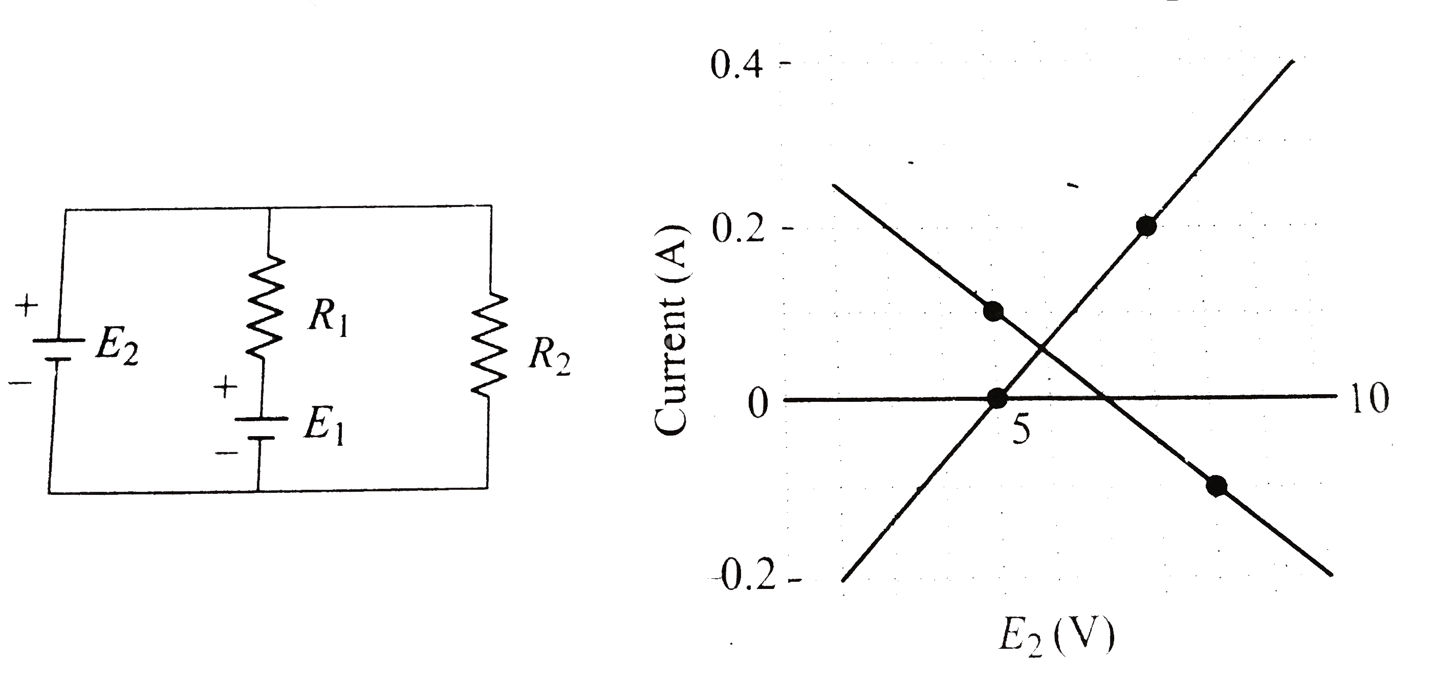
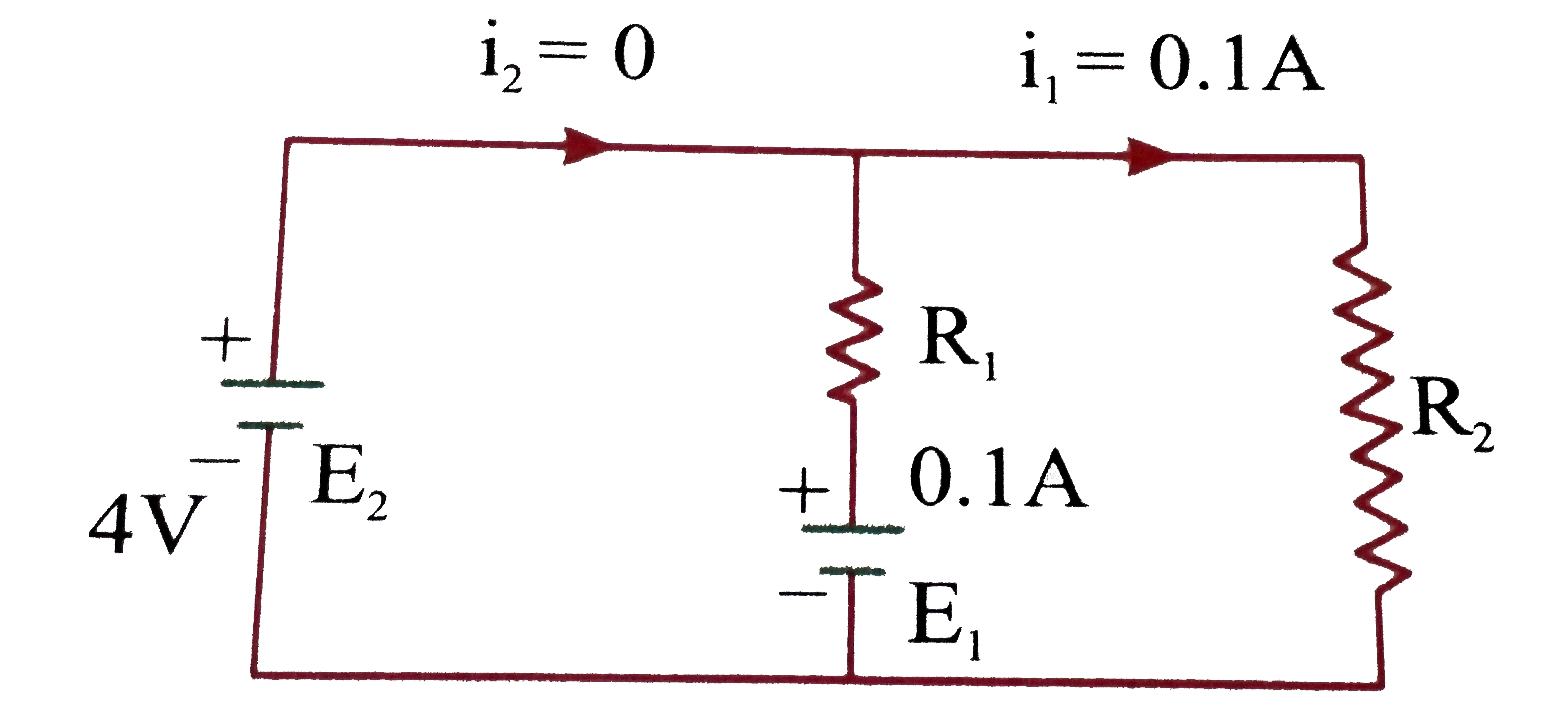
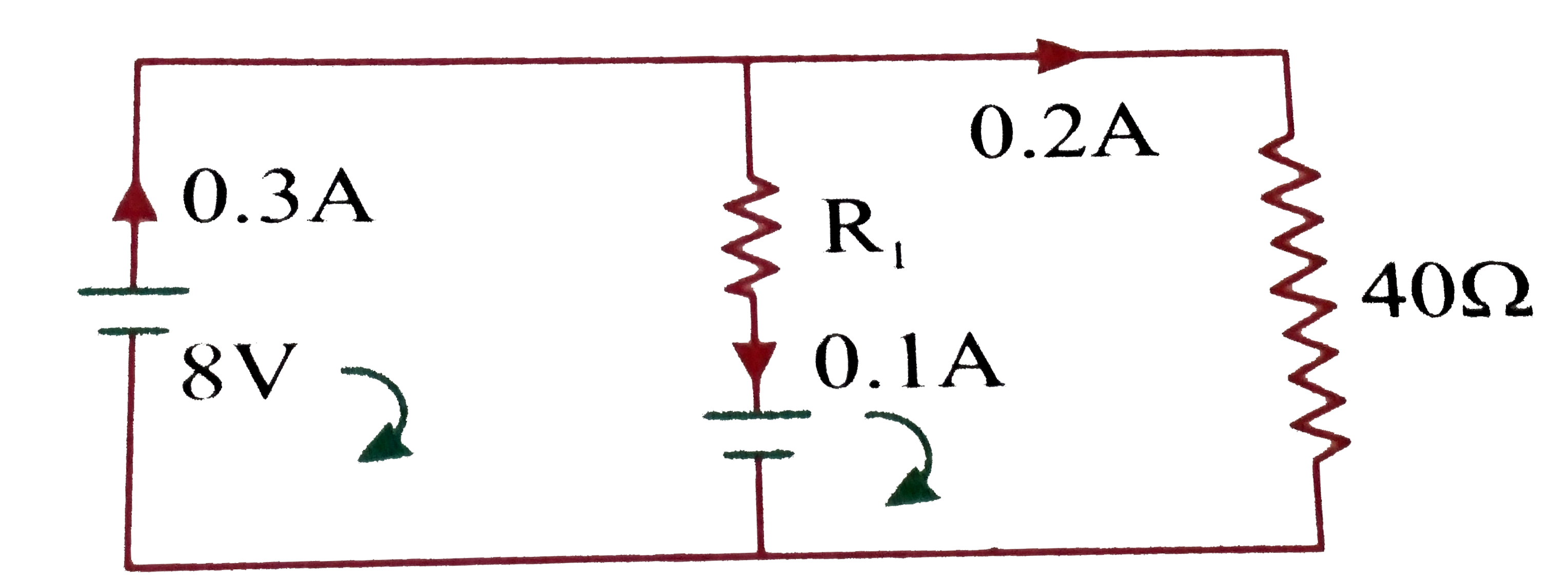
- In the circuit given in the figure, both batteries are ideal . Emf E1 ...
Text Solution
|
- In the circuit givenn below, both batteries are ideal. EMF E(1) of bat...
Text Solution
|
- In the circuit given in the figure, both batteries are ideal . Emf E1 ...
Text Solution
|
- In the following circuit, the current through the resistor R (=2Omega)...
Text Solution
|