A
B
C
D
Text Solution
Verified by Experts
The correct Answer is:


Topper's Solved these Questions
Similar Questions
Explore conceptually related problems
NARAYNA-ALTERNATING CURRENT-LEVEL - V
- The series RLC circuit in resonance is called:
Text Solution
|
- In a series R-L-C circuit, the frequency of the source is half of the ...
Text Solution
|
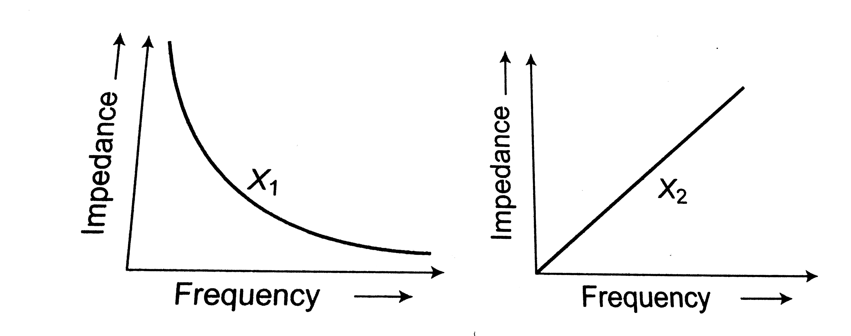
- The graphs given below depict the dependence of two reactive impedence...
Text Solution
|
- In which of the following electrical applianes will AC fail to functio...
Text Solution
|
- Instantaneous values of current and e.m.f in an AC circuit are I=I//s...
Text Solution
|
- The rms value of an ac of 50Hz is 10A. The time taken by an alternatin...
Text Solution
|
- The voltage time (V-t) graoh for triangular wave having peak value (V0...
Text Solution
|
- The average value for the saw-tooth voltage of peak value of V(0) over...
Text Solution
|
- An alternating voltage is given by: e = e(1) sin omega t + e(2) cos om...
Text Solution
|
- If i= t^(2), 0 lt t lt T then r.m.s. value of current is
Text Solution
|
- An alternating voltage V = 100 sin omega t is applied across an LCR ci...
Text Solution
|
- The rms and the average value of the voltage wave shown in figure are
Text Solution
|
- If i(1) = i(0) sin (omega t), i(2) = i(0(2)) sin (omega t + phi), then...
Text Solution
|
- The average and effective values for the waveshaphe shown in figure ar...
Text Solution
|
- Calculate the reading which will be given by a hot-wire voltmeter if i...
Text Solution
|
- An alternating current I in an inductance coil varies with time t acco...
Text Solution
|
- Find the rms and average value of the wavefrom shown in figure
Text Solution
|
- Determine the rms value of a semi-circular current wave which has a ma...
Text Solution
|
- An electric bulb is designed to operate at 12 volts DC. If this bulb ...
Text Solution
|
- The current in a discharging LR circuit is given by I = i0 e^(-t/tau) ...
Text Solution
|