Home
Class 12
PHYSICS
In a series C-R circuit shown in figureu...

In a series `C-R` circuit shown in figureure, the applied voltage is `10 V` and the voltage across capacitor is found to`8 V`. The voltage across `R`, and the phase difference between current and the applied voltage will respectively be
.

A

`6 V, tan^(-1) ((4)/(4))`

B

`3V, tan^(-1)((3)/(4))`

C

`6V, tan^(-1)((5)/(3))`

D

`3V, tan^(-1)((4)/(3))`

Text Solution

Verified by Experts

The correct Answer is:
A

`V^(2) = V_(R )^(2) + V_(C )^(2) implies V_(R ) = 6` volt
`phi = tan^(-1) ((X_(C ))/(R )) = tan^(-1) ((V_(C ))/(V_(R )))`
`tan^(-1) ((8)/(6)) = tan^(-1) ((4)/(3))`
Promotional Banner

Topper's Solved these Questions

  • ALTERNATING CURRENT

    NARAYNA|Exercise LEVEL - VI|120 Videos
  • ALTERNATING CURRENT

    NARAYNA|Exercise LEVEL - I (H.W)|23 Videos
  • ALTERNATING CURRENT

    NARAYNA|Exercise LEVEL - IV NCERT Based Questions|15 Videos
  • ATOMIC PHYSICS

    NARAYNA|Exercise LEVEL-II (H.W)|14 Videos

Similar Questions

Explore conceptually related problems

In a series CR circuit shown in figure,the applied voltage is 10V and the voltage across capacitor is found to be 8V

In series LCR circuit, the phase difference between voltage across L and voltage across C is

In a series L-C circuit, the applied voltage is V_0. if omega is very low, then the voltage drop across the inductor V_L and capacitor V_C are .

In a LCR series circuit, if the phase difference between applied voltage and current is zero then

In an L-R circuit, an inductance of 0.1 H and a resistance of 1 Omega are connected in series with an ac source of voltage V = 5 sin 10 t. The phase difference between the current and applied voltage will be

In an L-R circuit, an inductance of 0.1 H and a resistance of 1 Omega are connected in series with an ac source of voltage V = 5 sin 10 t. The phase difference between the current and applied voltage will be

In an L-C-R circuit, if V is the effective value of the applied voltage V_(R) is the voltage across R, V_(L) is the effective voltage across L, V_(C) is the effective voltage across C, then

In a series L-C-R circuit, currenrt in the circuit is 11A when the applied voltage is 220 V . voltage across the caspcitor is 200 V . If the value of resistor is 20 Omega , then the voltage across the unknown inductor is

An Ac voltage V=V_0 sin 100t is applied to the circuit, the phase difference between current and voltage is found to be pi/4 , then .

NARAYNA-ALTERNATING CURRENT-LEVEL - V
  1. A series combination of R,LC is connected to an a.c source. If the res...

    Text Solution

    |

  2. In an a.c. Circuit the voltage applied is E=E(0) sin (omega)t. The res...

    Text Solution

    |

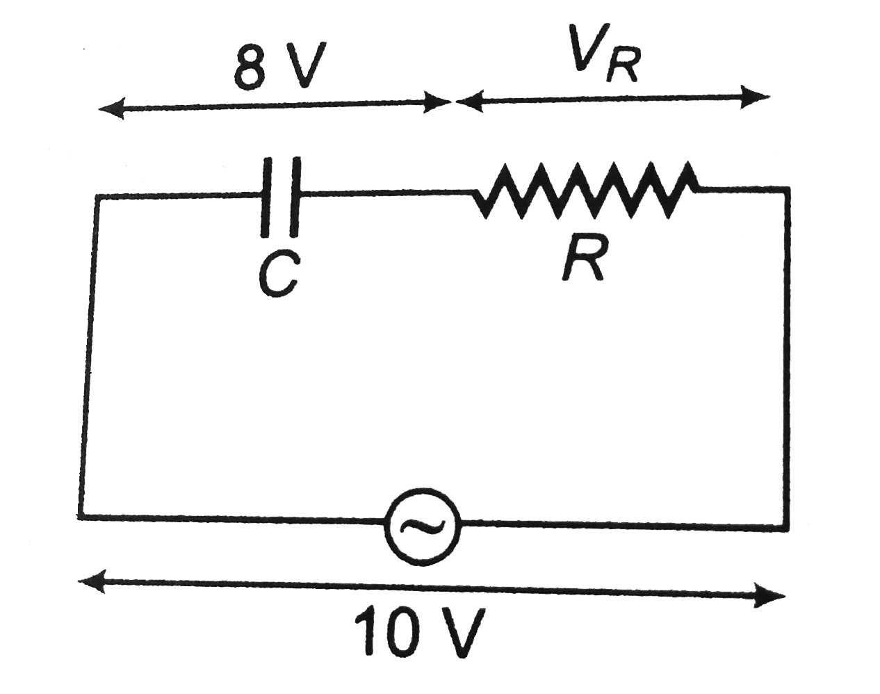
  3. In a series C-R circuit shown in figureure, the applied voltage is 10 ...

    Text Solution

    |

  4. An inductor of inductance L and ressistor of resistance R are joined i...

    Text Solution

    |

  5. Power loss in AC circuit will be minimum when

    Text Solution

    |

  6. In the circuit, as shown in the figure, if the value of R.M.S current ...

    Text Solution

    |

  7. The impedance of a sereis RL circuit is same as the series RC circuit ...

    Text Solution

    |

  8. A current source sends a current I=(i0) cos (omegat), When connected a...

    Text Solution

    |

  9. A combination of elements is enclosed in a black box an the voltage an...

    Text Solution

    |

  10. A high impedance AC voltmeter is connected in turn across the inductor...

    Text Solution

    |

  11. In a black box of unknown elements (L or R or any other combination), ...

    Text Solution

    |

  12. A given alternating current has an rms value of 5.6 ampere. If this cu...

    Text Solution

    |

  13. In an a.c circuit, V & I are given by V = 100 sin (100 t) volt. I = ...

    Text Solution

    |

  14. In R-L-C series circuit, we have same current at angular frequencies o...

    Text Solution

    |

  15. A choke coil of resistance R and inductance L is connected to A.C sour...

    Text Solution

    |

  16. When two A.C generators of emfs V(1) and V(2) and same frequency conne...

    Text Solution

    |

  17. At resonance of the given series R-L-C circuit:

    Text Solution

    |

  18. If the reading of the voltmeters vary with time as: V(1) = 20 sin omeg...

    Text Solution

    |

  19. In a series LCR circuit, at the frequencies f(1) and f(2) of AC source...

    Text Solution

    |

  20. In the figure, which of the phasor diagrams represents RLC circuit dri...

    Text Solution

    |