A
B
C
D
Text Solution
Verified by Experts
The correct Answer is:


Topper's Solved these Questions
Similar Questions
Explore conceptually related problems
NARAYNA-ALTERNATING CURRENT-LEVEL - V
- A choke coil of resistance R and inductance L is connected to A.C sour...
Text Solution
|
- When two A.C generators of emfs V(1) and V(2) and same frequency conne...
Text Solution
|
- At resonance of the given series R-L-C circuit:
Text Solution
|
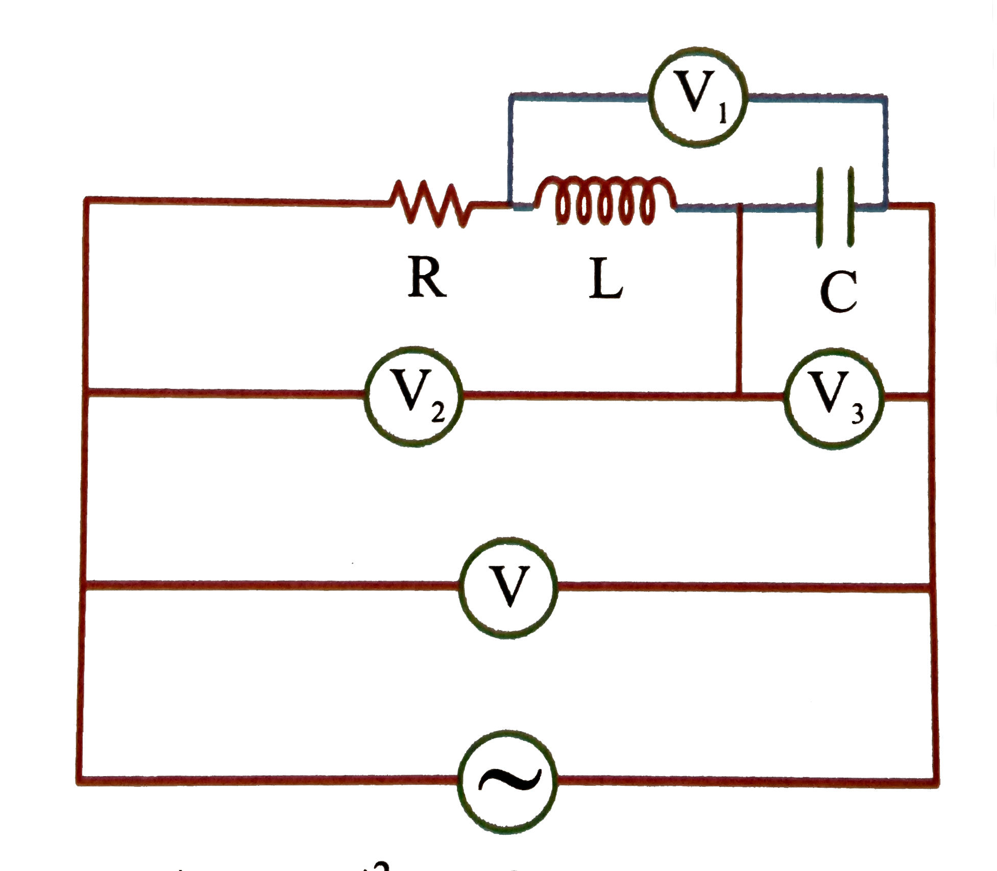
- If the reading of the voltmeters vary with time as: V(1) = 20 sin omeg...
Text Solution
|
- In a series LCR circuit, at the frequencies f(1) and f(2) of AC source...
Text Solution
|
- In the figure, which of the phasor diagrams represents RLC circuit dri...
Text Solution
|
- In LCR circuit at resonance current in the circuit is 10 sqrt(2) A. If...
Text Solution
|
- A pure resistive circuit element X when connected to an sinusoidal AC ...
Text Solution
|
- An A.C circuit contains a resistor 'R' an inductor 'L' and a capacitor...
Text Solution
|
- An alternative voltage V = 10 sin omega t (in volts) is applied across...
Text Solution
|
- A radio tuner has a frequency range from 500 kHz to 5 MHz. If its LC c...
Text Solution
|
- In a series LCR circuit the frequency of a 10 V, AC voltage soure is a...
Text Solution
|
- A resistor of resistance 100 Omega is connected to an AC source epsilo...
Text Solution
|
- A lamp consumes only 50% of peak power in an a.c. circuit. What is the...
Text Solution
|
- Voltage and current for a circuit with two elements in series are expr...
Text Solution
|
- When an ac source of emfe=E(0) sin (100 t) is connected across a circu...
Text Solution
|
- The figure shows variation of R,X(L) and X(C) with frequency f in a se...
Text Solution
|
- Which of the following plots may represent the reactance of a series L...
Text Solution
|
- An inductor-coil , a capacitor and an AC source of rms voltage 24 V ar...
Text Solution
|
- A circuit consisting of a capacitor and a coil in series is connected ...
Text Solution
|