Home
Class 12
PHYSICS
Three capacitors of capacitances 5muF,2m...


Three capacitors of capacitances `5muF,2muF` and `2muF` are charged to 20 V, 30 V and 10 V respectively and then connected in the circuit with polarities as shown. The magnitude of charge flown through the battery after closing the switch S is

A

`25muC`

B

`40muC`

C

`50muC`

D

`75muC`

Text Solution

Verified by Experts

The correct Answer is:
A


`(q)/(5)+((q-40)/(2))+((q-120)/(2))=10`
`(6q)/(5)=90`
`q=75muC`
`therefore` magnitude of charge flown through the battery is
`Deltaq=100-75=25muC`
Promotional Banner

Topper's Solved these Questions

  • TEST PAPERS

    FIITJEE|Exercise PHYSICS|747 Videos
  • SIMPLE HARMONIC MOTION

    FIITJEE|Exercise Assignment Problems (Objective) (Level-II)|20 Videos
  • WORK, ENERGY AND POWER

    FIITJEE|Exercise COMPREHENSIONS ( Comprehension-II)|5 Videos

Similar Questions

Explore conceptually related problems

Two capacitors of capacitance 10 muF and 20 muF are charged to potential 20 V and 10 V respectively. If they are connected to share charges, then loss of energy is

Two capacitors of capacitance 2muF and 5muF are charged to a potential difference 100V and 50 V respectively and connected such that the positive plate of one capacitor is connected to the negative plate of the other capacitor after the switch is closed, the initial current in the circuit is 50 mA. the total resistance of the connecting wires is (in Ohm):

Three capacitors of capacitances 1 muF, 2 muF , and 2 muF , are cahrged up to the potential difference 30 V, 10 V , and 15 V , respectivly. If terminal A is connected with D C is connected with E and F is connected eith B, the find the charge flow in the ciruit and the final charge on the capacitors. .

Two capacitors of capacitances 1muF and 3muF are charged to the same voltages 5V. They are connected in parallel with oppositely charged plates connected together. Then

Three capacitors of capacitances 2muF, 2muF and 4muF are connected to a battery of 10V as shown in the figure. Calculate the effective capacitance of the circuit and charge on each capacitor.

Two capacitors of capacitances 3 muF and 6 muF , are charged to potentials 2V and 5V respectively. These two charged capacitors are connected in series. Find the potential across each of the two capacitors now.

Two capacitors of capacitance 2muF and 3muF respectively are charged to potential difference 20 V and 40 V respectively. Now the capacitors are connected in series with a resistance such that the positively charged plate of one capacitor is connected to the positively charged plate of the other. The initial current through the resistance is I_(0) . The potential difference across the 2muF capacitor at the instant the current has reduced to (I_(0))/(2) is_______ V.

Three capcaitors of capacities 1muF, 2muF and 3muF are charged by 10V, 20V and 30V respectively. Now positive plates of first two capacitors are connected with the negative plate of third capacitor on one side and negative plates of first wo capacitors are connectes with positive of third capacitor on the other side. Find a. common potential V b. final charges on different capacitors.

Three capacitors of capacitance 3 muF, 10 muF and 15 muF are connected in series to a voltage source of 100 V . The charge on 15 muF is

FIITJEE-TEST PAPERS-PHYSICS
  1. A point charge 'q' is placed at the centre of left circular end of a c...

    Text Solution

    |

  2. Two concentric spherical conducting shells of radii 'a' and 2a are ini...

    Text Solution

    |

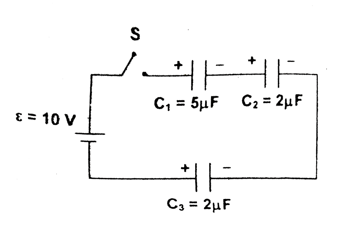
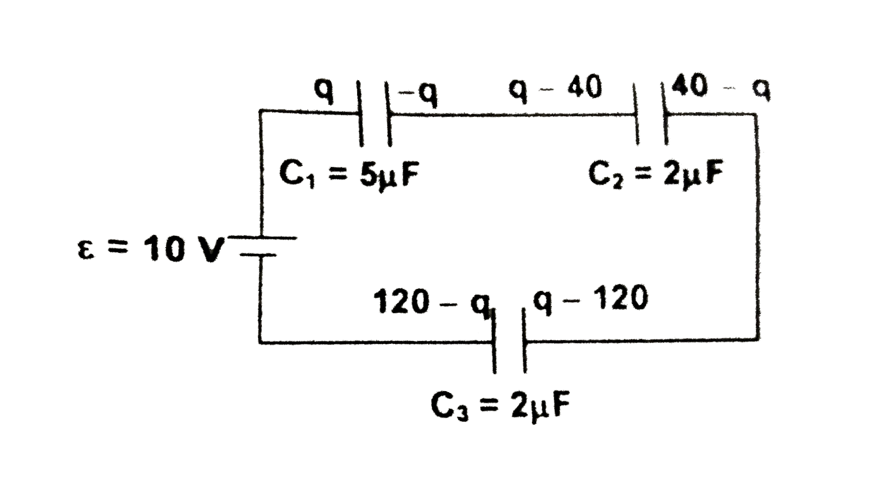
  3. Three capacitors of capacitances 5muF,2muF and 2muF are charged to 20 ...

    Text Solution

    |

  4. Three concentric spherical conducting shells A, B and C of radii a, 2a...

    Text Solution

    |

  5. In the circuit shown the cell will deliver maximum power to the networ...

    Text Solution

    |

  6. In the circuit shown, all the capacitors are initially uncharged. The ...

    Text Solution

    |

  7. A particle of charge 'q' and mass 'm' enters a uniform magnetic field ...

    Text Solution

    |

  8. A conducting wire MN carrying a current I is bent into the shape as sh...

    Text Solution

    |

  9. A conducting loop carrying current 'l' is bent into two halves and pla...

    Text Solution

    |

  10. A conducting wire carrying a current I is bent into the shape as shown...

    Text Solution

    |

  11. An infinitely long cylinderical wire of radius R is carrying a current...

    Text Solution

    |

  12. A circular conducting ring of radius 'a' is rolling with slipping on a...

    Text Solution

    |

  13. A time varying magnetic field B=krt (where k is a constant r is the ra...

    Text Solution

    |

  14. A conducting rod MN of mass m and length 'l' is placed on parallel sm...

    Text Solution

    |

  15. Charge 'q' is uniformly distributed along the length of a non-coductin...

    Text Solution

    |

  16. Initially capacitor 'A' is charged to a potential drop epsilon and cap...

    Text Solution

    |

  17. In the circuit shown, switch's is closed at t=0. then the ratio (U(1))...

    Text Solution

    |

  18. In the circuit shown the average power developed in the resistor R(1) ...

    Text Solution

    |

  19. A uniform potentiometer wire AB of length 100 cm has a resistance of 5...

    Text Solution

    |

  20. A small spherical conductor 'A' of radias 'a' is initially charged to ...

    Text Solution

    |