Text Solution
Verified by Experts
The correct Answer is:


Topper's Solved these Questions
Similar Questions
Explore conceptually related problems
ARIHANT-ALTERNATING CURRENT-level-2
- A series LCR circuit containing a resistance of 120 Omega has angular ...
Text Solution
|
- A resistance (R), inductance (L) and capacitance (C) are connected in ...
Text Solution
|
- A FM radio receiver has a series LCR circuit with L = 1 muH, and R = 1...
Text Solution
|
- In the circuit shown in Figure, the source has a rating of 15 V, 100 H...
Text Solution
|
- A box has a large electric circuit inside it. When it was connected to...
Text Solution
|
- In the circuit shown the source voltage is given as v = V(0) sin omega...
Text Solution
|
- In the circuit shown the transformer is ideal with turn ration(N(1))/...
Text Solution
|
- A transformer with 20 turns in its secondary coil is used to step down...
Text Solution
|
- Two boys are holding a wire, standing 4 m apart. The wire sags in the ...
Text Solution
|
- In a series LCR circuit the phasors corresponding to voltage across re...
Text Solution
|
- A series LCR circuit having resistance R, capacitance C and inductance...
Text Solution
|
- In a series LCR circuit, the frequencies at which the current amplitud...
Text Solution
|
- A series RLC circuit is in resonance with a source of frequency omega(...
Text Solution
|
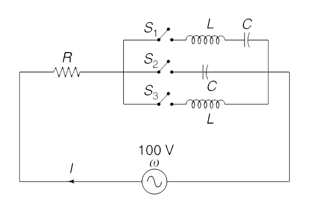
- In the circuit shown in the figure, one of the three switches is kept ...
Text Solution
|
- A village with a demand of 800 kW electric power at 220 V is located 3...
Text Solution
|