Home
Class 12
PHYSICS
The resistance of a germanium junction d...

The resistance of a germanium junction diode whose `V-I` is shown in figure is `(V_(k)=0.3 V)`

A

`5 k Omega`

B

`0.2 k Omega`

C

`2.3 k Omega`

D

`((10)/(2.3))k Omega`

Text Solution

Verified by Experts

The correct Answer is:
B
Doubtnut Promotions Banner Mobile Dark
|

Topper's Solved these Questions

  • ELECTRONICS

    ERRORLESS |Exercise Selv Evaluation Test|23 Videos
  • ELECTRONICS

    ERRORLESS |Exercise Objective Questions|12 Videos
  • ELECTRON, PHOTON, PHOTOELECTRIC EFFECT AND X-RAYS

    ERRORLESS |Exercise Self Evaluation Test|3 Videos
  • ELECTROSTATICS

    ERRORLESS |Exercise Ordinary Thinking Objective Questions (Electric Flux and Gauss.s Law)|28 Videos

Similar Questions

Explore conceptually related problems
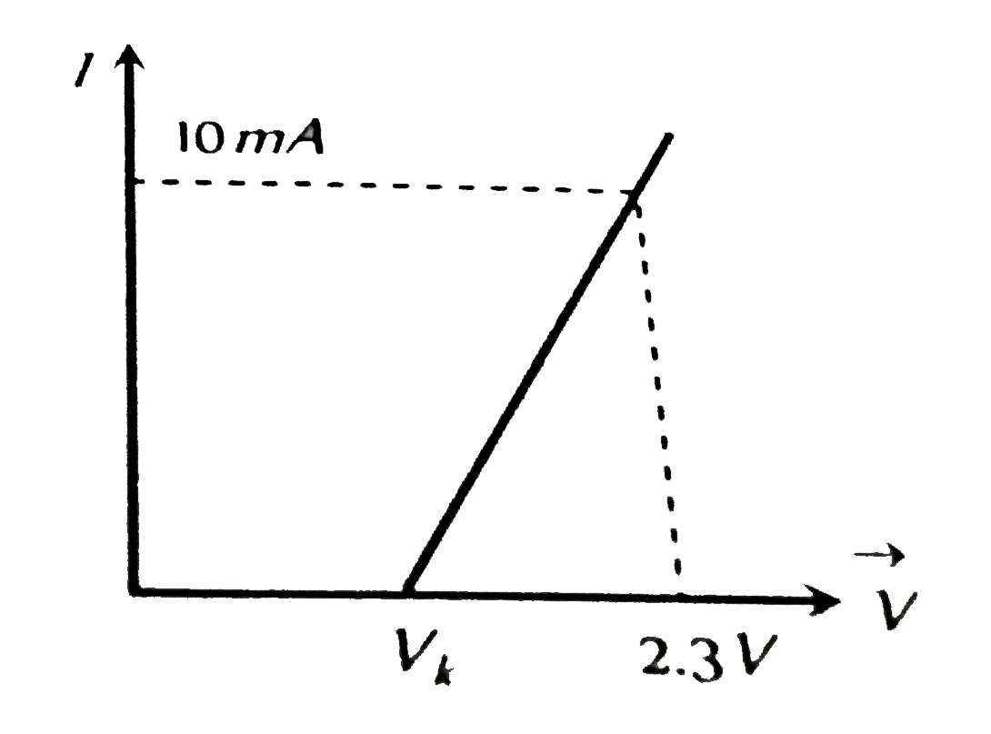
The resistance of a germanium junction diode, whose V –I characteristics is shown in the figure , will be ( v_k= 0.3 V ) .

Name the junction diode whose I-V characteristics are shown adjoining

Knowledge Check

  • The V-I characterisctic for a p-n junction diode is plotted as shown in the figure. From the plot we can conclude that [V_(b)to breakdown voltage, V_(k)to knee voltage]

    A
    the forward bias resistance of diode is very high, almost infinity for small values of V and after a certain value it becomes very low
    B
    the reverse bias resistance of diode is very high in the beginning upto breakdown voltage is not achieved
    C
    both forward and reverse bias resistances are same for all voltages
    D
    both (A) and (B) are correct
  • The V-I characteristic of a silicon diode is shown in figure . The resistance of the diode at I_D =15 mA is

    A
    `5 Omega`
    B
    `10 Omega`
    C
    `2 Omega`
    D
    `20 Omega`
  • What is the base resistance R_(B) in the circuit as shown in figure , if beta_(d.c.) = 90, V_(BE) = 0.7 V, V_(CE) =4V?

    A
    `29 K Omega`
    B
    `82 K Omega`
    C
    `108 K Omega`
    D
    `55 K Omega`
  • Similar Questions

    Explore conceptually related problems

    A cell emf 3V and internal resistance 0.75Omega is connected to a nonlinear conductor whose V-I g raph is shown in figure obtain graphically the current drawn from the cell and its terminal voltage.

    Voltage V v/s I graph is shown in the figure.

    Two junction diodes, one of germanium (Ge) and other of silicon (Si) are connected as shown in fig to a battery of 12 V and a load resistance 10 kOmega . The germanium diode conducts at 0.3 V and silicon diode at 0.7 V . When current flows in the circuit, the potential of terminal Y will be .

    Name the junction diode whose I-V characteristics are drawn below.

    Name the junction diode whose I-V characteristics are drawn below: