A
B
C
D
Text Solution
Verified by Experts
The correct Answer is:


Topper's Solved these Questions
CAPACITANCE
PHYSICS GALAXY - ASHISH ARORA|Exercise ADVANCE MCQS|26 VideosCAPACITANCE
PHYSICS GALAXY - ASHISH ARORA|Exercise UNSOLVED NUMERICAL PROBLEMS|40 VideosCAPACITANCE
PHYSICS GALAXY - ASHISH ARORA|Exercise CONCEPTUAL MCQA|32 VideosATOMIC PHYSICS
PHYSICS GALAXY - ASHISH ARORA|Exercise Unsolved Numerical Problems|39 VideosCURRENT ELECTRICITY
PHYSICS GALAXY - ASHISH ARORA|Exercise All Questions|389 Videos
Similar Questions
Explore conceptually related problems
PHYSICS GALAXY - ASHISH ARORA-CAPACITANCE-NUMERICAL MCQS
- A circuit element is placed in a blackbox. At t=0, a switch is closed ...
Text Solution
|
- Two parallel plate capacitors of capacitances C and 2C are connected i...
Text Solution
|
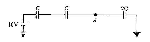
- In a circuit shown in the figure, what is potential of point A?
Text Solution
|
- Two long coaxial cylindrical metal tubes stand on an insulatiog floor ...
Text Solution
|
- Find the time constant for the given RC circuits in correct order (in ...
Text Solution
|
- The capacities and connection of five capacitors are shown in the adjo...
Text Solution
|
- In the circuit shown here C(1) = 6muF, C2 = 3muF and battery B = 20V. ...
Text Solution
|
- Three plates A, B, C each of area 50 cm^(2) have separation 3 mm betwe...
Text Solution
|
- A fully charged capacitor has a capacitance 'C'. It is discharged thro...
Text Solution
|
- A parallel plate capacitor with air between the plates has capacitance...
Text Solution
|
- Six plates each of area A arranged as shown· in figure. The separation...
Text Solution
|
- Six capacitors each of capacitance of 2muF are connected as shown in t...
Text Solution
|
- What is equivalent capacitance of ladder circuit shown in figure betwe...
Text Solution
|
- Find the equivalent capacitance between terminals A and B in the circu...
Text Solution
|
- Circuit in figure shows three capacitors with capacitance and their br...
Text Solution
|
- A 2muF capacitor is charged as shown in the figure. The percentage of ...
Text Solution
|
- For the circuit shown in figure, which of the below options given is/a...
Text Solution
|
- In the circuit shown, a potential difference of 60V is applied acrodd....
Text Solution
|
- Four identical capacitors are connected in series with a 10 V battery...
Text Solution
|
- Find the equivalent capacitance across A and B for the arrangement sho...
Text Solution
|