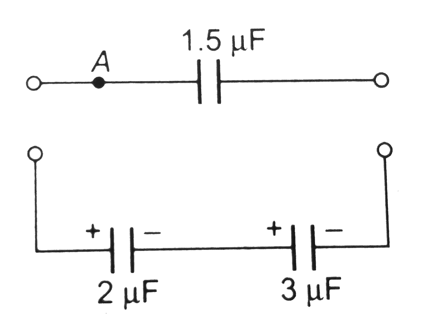
Home
Class 12
PHYSICS
Two capacitors of 2muF and 3muF are char...

Two capacitors of `2muF` and `3muF` are charged to `150 V` and `120 V`, respectively. The plates of capacitor are connected as shown in the figure. An uncharged capacitor of capacity `1.5muF` falls to the free end of the wire. Then

A

Charge on `1.5muF` capacitoris `180muC`

B

Charge on `2muF` capacitor is `120muC`

C

Positive charge flows through `A` from right to left

D

Positive charge flows through `A` from left to right

Text Solution

Verified by Experts

The correct Answer is:
A, B, D
Promotional Banner

Topper's Solved these Questions

  • CAPACITANCE

    PHYSICS GALAXY - ASHISH ARORA|Exercise UNSOLVED NUMERICAL PROBLEMS|40 Videos
  • CAPACITANCE

    PHYSICS GALAXY - ASHISH ARORA|Exercise NUMERICAL MCQS|56 Videos
  • ATOMIC PHYSICS

    PHYSICS GALAXY - ASHISH ARORA|Exercise Unsolved Numerical Problems|39 Videos
  • CURRENT ELECTRICITY

    PHYSICS GALAXY - ASHISH ARORA|Exercise All Questions|389 Videos

Similar Questions

Explore conceptually related problems

In the circuit shown in figure charge stored in the capacitor of capacity 5muF is

Two capacitors A and B with capacities 3muF and 2muF are charged to a potential difference of 100 V and 180V , respectively. The plates of the capacitors are connected as show in figure with one wire of each capacitor free. The upper plate of A is positive and that of B is negastive. An uncharged 2muF capcitor C with lead wires falls on the free ends to complete the circuit. Calculate a. the final charge on the three capacitors. b. the amount of electrostatic energy stored in the system before and after completion of the circuit.

Two cellls, two resistance and two capacitors are connected as shown in figure. The charge on 2muF capacitors is

Two capacitors A and B with capacities 3 muF and 2 muF are charged to a potential differece of 100 V and 180 V , respectively. The plates ot the capacitors are connected as shown in, with one wire free from each capacitor. The upper plate of A is positive and that of B is negative An uncharged 2muF capacitor C with lead wires falls on the free ends to complete the circuit. i. Calculate the final charge on the three capacitors, ii. Find the amount of electrostatic energy stored in the system before and after the completion of the circuit. .

Two capacitors A and B with capacitors 3 muF and 2 muF are charged to a potential difference of 100 V and 180 V respectively. One plate of two capacitors are connected as shown. Now switch S is closed so as to connect a cell of 100 V to the free plates of two capacitors. (a) Find charge on the two capacitors after the switch is closed. (b) Calculate heat generated in the circuit

For the circuit shown in figure the charge on 4muF capacitor is

Two capacitors of capacitance 10 muF and 20 muF are charged to potential 20 V and 10 V respectively. If they are connected to share charges, then loss of energy is

For the arrangement shown in the figure, the charge on the 4muF capacitor is

Two capacitors of capacitances 3 muF and 6 muF , are charged to potentials 2V and 5V respectively. These two charged capacitors are connected in series. Find the potential across each of the two capacitors now.

Three capcaitors of capacities 1muF, 2muF and 3muF are charged by 10V, 20V and 30V respectively. Now positive plates of first two capacitors are connected with the negative plate of third capacitor on one side and negative plates of first wo capacitors are connectes with positive of third capacitor on the other side. Find a. common potential V b. final charges on different capacitors.

PHYSICS GALAXY - ASHISH ARORA-CAPACITANCE-ADVANCE MCQS
  1. Capacitor C(1) of the capacitance 1muF and another capacitor C(2) of c...

    Text Solution

    |

  2. A capacitor of capacity C(0) is conneted to a battery of emfV(0) When ...

    Text Solution

    |

  3. A dielectric slab fills the space between the square plates of a paral...

    Text Solution

    |

  4. In a spherical capacitor,-we have two concentric spherical shells, the...

    Text Solution

    |

  5. A parallel plate air capacitor is connected to a battery. The quantiti...

    Text Solution

    |

  6. A capacitor with no dielectric is connected to a battery at t=0.Consid...

    Text Solution

    |

  7. Each plate of a parallel plate capacitor has a charge q on it. The cap...

    Text Solution

    |

  8. Figure shows three circuits, each consisting of a switch and two capac...

    Text Solution

    |

  9. A dielectric slab of thickness d is inserted in a parallel plate capa...

    Text Solution

    |

  10. In the circuit shown, the potential difference across the 3muF capacit...

    Text Solution

    |

  11. Two identical parallel plate capacitors of same dimensions joined in s...

    Text Solution

    |

  12. A parallel plate capacitor is first connected to a constant voltage so...

    Text Solution

    |

  13. In a parallel-plate capacitor, the region between the plates is filled...

    Text Solution

    |

  14. In a parallel plate capacitor, the region between the plates is fille...

    Text Solution

    |

  15. A parallel plate capacitor is connected across a source of covstant po...

    Text Solution

    |

  16. Identical dielectric slabs are inserted into two identical capacitors ...

    Text Solution

    |

  17. A parallel plate air capacitor is connected to a battery. If plates of...

    Text Solution

    |

  18. When two identical capacitors are charged individually to different po...

    Text Solution

    |

  19. The plates of a parallel plate capacitor are, not exactly parallel. Th...

    Text Solution

    |

  20. Two capacitors of 2muF and 3muF are charged to 150 V and 120 V, respec...

    Text Solution

    |