


Topper's Solved these Questions
Similar Questions
Explore conceptually related problems
PHYSICS GALAXY - ASHISH ARORA-CURRENT ELECTRICITY-All Questions
- Find out the magnitude of resistance X in the circuit shown in figure,...
Text Solution
|
- In the circuit shown in fig. calculate the following: a. Potential d...
Text Solution
|
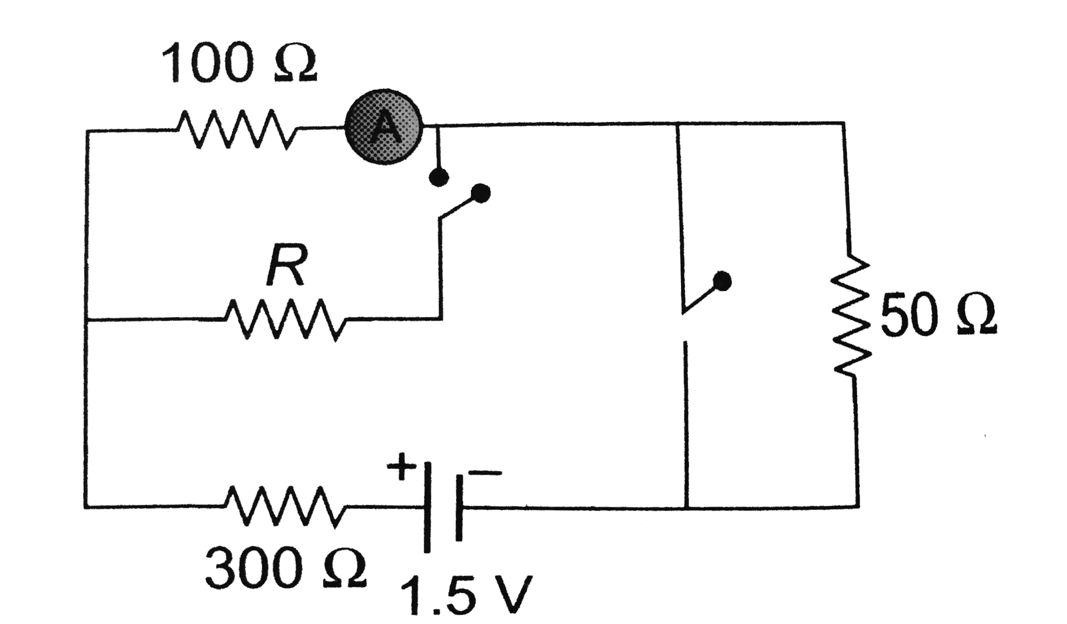
- In the circuit shown in figure the reading of ammeter is the same with...
Text Solution
|
- For the following diagram the galvanometer shows zero deflection then ...
Text Solution
|
- Find the equivalent resistance of the circuit shown in figure-3.64 acr...
Text Solution
|
- Find current in the branch CD of the circuit
Text Solution
|
- In the network of resistances shown in figure-3.88. ABCDA is a uniform...
Text Solution
|
- Determine the current l supplied by the battery in the circuit shown i...
Text Solution
|
- What will be the change in the resistance of a circuit consisting of f...
Text Solution
|
- The figure shows a network of resistor each heaving value 12 Omega. Fi...
Text Solution
|
- Find the steady state charge stored in the capacitor.
Text Solution
|
- In the cirucit shown in figure-3.250, find the steady state charges on...
Text Solution
|
- Three parallel plate capacitors C(1) = 4 muF,C(2) =2mu F,C(3) = 6muF w...
Text Solution
|
- Determine the current through the battery in the circuit shown in figu...
Text Solution
|
- To the cirucit shown in figure-3.254 a capacitor of capacitance 5muF i...
Text Solution
|
- Calculate the charge on capacitor A in the circuit shown in figure-3.2...
Text Solution
|
- In the circuit shown in figure E1, 2E2=20V, R1=R2=10kOmega and C=1muF....
Text Solution
|
- A capacitor of capacitance C(1)=0.1F is charged by a battery of EMF E(...
Text Solution
|
- An isolated parallel plate capacitor has circular plates of radius 4.0...
Text Solution
|
- A circuit consists of a source of a constant emf xi and a resistance ...
Text Solution
|