A
B
C
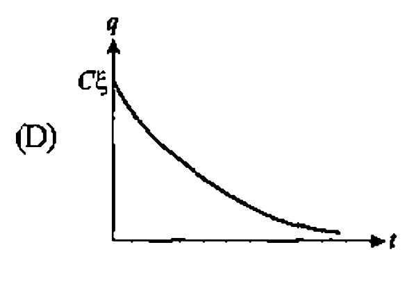
D
Text Solution
Verified by Experts
The correct Answer is:


Topper's Solved these Questions
Similar Questions
Explore conceptually related problems
PHYSICS GALAXY - ASHISH ARORA-CURRENT ELECTRICITY-All Questions
- In the circuit shown, switch Sis closed att=O. Let i(1) and i(2) be th...
Text Solution
|
- A lmuF capacitor is connected in the circuit shown below. The EMF of t...
Text Solution
|
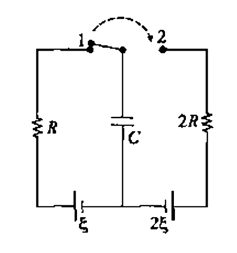
- In the circuit shown in figure-3.311, the switch is shifted from posit...
Text Solution
|
- The capacitor shown in figure-3.312-(a) is charged to steady state by ...
Text Solution
|
- The deflection in a galvanometer fulls from 50 divisions to 20 divisio...
Text Solution
|
- If 2% of the main current is to be passed through the galvanometer of ...
Text Solution
|
- If the length of the filament ofa heater is reduced by 10% the power o...
Text Solution
|
- A 2.0V potentiometer is used to determine the internal resistance ofa ...
Text Solution
|
- The drift velocity of free electrons in a conductor is v, when a curre...
Text Solution
|
- A galvanometer is to be converted into an ammeter or voltmeter. In whi...
Text Solution
|
- In the given circuit current flowing through the resistance 20Omega is...
Text Solution
|
- Two batteries one of the emf3V, internal resistance In and the other o...
Text Solution
|
- A part of a circuit is shown in figure. Here reading of ammeter is 5A ...
Text Solution
|
- Two resistances are connected in two gaps of a metre bridge. The balan...
Text Solution
|
- In the given circuit, the voltmeter reads SV. The resistance of the vo...
Text Solution
|
- The wire of potentiometer has resistance 4Omega and length Im. It is c...
Text Solution
|
- Two identical batteries, each of EMF 2V and internal resistance r =1Om...
Text Solution
|
- The potential difference between points A and Bin the circuit shown in...
Text Solution
|
- Find the ratio ofcurrents as measured by ammeter in two cases when the...
Text Solution
|
- A galvanometer has a resistance of 3663Omega. A shunt Sis connected a...
Text Solution
|