Home
Class 12
PHYSICS
Three voltmeters all having different re...

Three voltmeters all having different resistance, are joined as shown. When some potential difference is applied acros `A` and `B`, their readings are `V_1,V_2` and `V_3.` Then

A

`V_(1)=V_(2)`

B

`V_(1) ne V_(2)`

C

`V_(1)+V_(2)=V_(3)`

D

`V_(1)+V_(2)gt V_(3)`

Text Solution

Verified by Experts

Promotional Banner

Topper's Solved these Questions

  • CAPACITANCE

    PHYSICS GALAXY - ASHISH ARORA|Exercise UNSOLVED NUMERICAL PROBLEMS|40 Videos
  • ELECTROMAGNETIC INDUCTION AND ALTERNATING CURRENT

    PHYSICS GALAXY - ASHISH ARORA|Exercise Advance MCQs|33 Videos

Similar Questions

Explore conceptually related problems

Three ammeters 1, 2, and 3 of resistances R_(1). R_(2) and R_(3) respectively are joined as shown. When some potential difference is applied across the terminals P and Q, their readings are I_(1), I_(2) and I_(3) , respectively. Then

A, B and C are voltmeters of resistances R, 1.5R and 3R respectively. When some potential difference is applied between x and y the voltmeter readings are V_A, V _B and V_C, then

A,B and C are voltmeters of resistance R, 1.5 R and 3R respectively as shown in the figure. When some potential difference is applied between X and Y, the voltmeter reading are V_A , V_B and V_C respectively.

Three voltmeters A, B and C having resistances R, 1.5 R and 3 R respectively are used in a circuit as shown. When a potential difference is applied between X and Y, the readings of the voltmeters are V_1, V_2 and V_3 respectively. Then :

When a potential difference (V) is applied across a conductor, the thermal speed of electrons is

Three voltmeters are connected as shown. A potential difference has been applied between A and B . On closing the swich S , readings of voltmeters?

In the circuit shown, a potential difference of 60V is applied across AB. The potential difference between the point M and N is

PHYSICS GALAXY - ASHISH ARORA-CURRENT ELECTRICITY-All Questions
  1. Two cells of emf E1=6V and E2=5 are joined in parallel with same polar...

    Text Solution

    |

  2. Three ammeters A,B, and C of resistances RA,Rb and RC respectively are...

    Text Solution

    |

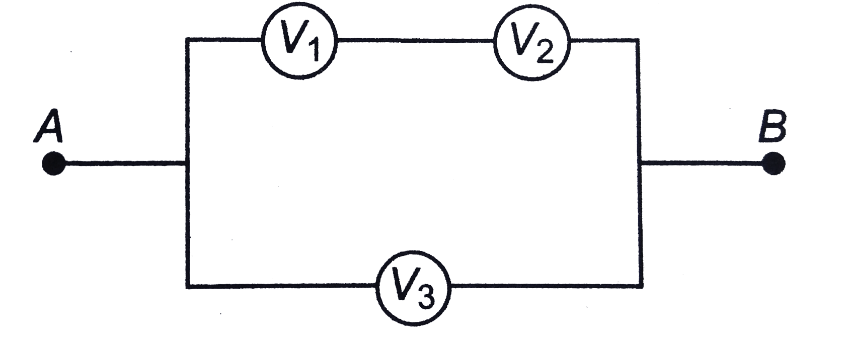
  3. Three voltmeters all having different resistance, are joined as shown....

    Text Solution

    |

  4. Two conductors made of the same material have lengths L and 2L but hav...

    Text Solution

    |

  5. In the part of circuit shown in figure-3.364

    Text Solution

    |

  6. In the poteniometer experiement shown in figure, the null point length...

    Text Solution

    |

  7. In the circuit shown in figure, reading of ammeter will

    Text Solution

    |

  8. In the circuit shown in figure it is given that Vb-Va=2 volt. Choose t...

    Text Solution

    |

  9. Each resistance of the network shown in figure is r. Net resistance be...

    Text Solution

    |

  10. A capacitor of 2F (practically not possible to have a capacity of 2F) ...

    Text Solution

    |

  11. In the circuit shown in the figure, switch S is closed at time t=0. Se...

    Text Solution

    |

  12. Capacitor C1 of capacitance 1 micro-farad and capacitor C2 of capacita...

    Text Solution

    |

  13. An electrical circuit is shown in the given figure. The resistance of ...

    Text Solution

    |

  14. Two parallel plate capacitor of capacitance 2C and C are charged to th...

    Text Solution

    |

  15. Analyze the given circuit in the steady state condition. Charge on the...

    Text Solution

    |

  16. A capacitor of capacitance 5muF is connected to a source of constant e...

    Text Solution

    |

  17. The figure-3.375 shows two circuits with a charged capacitor that is t...

    Text Solution

    |

  18. In Fig, E =5 volt , r = 1 Omega, R(2) = 4 Omega, R(1) = R(3) = 1 Omeg...

    Text Solution

    |

  19. A circuit shown in Fig, has resistances R(1) = 20 Omega and R(2) = 30...

    Text Solution

    |

  20. A capacitor of capacitance C= 500 mu F is connected to a source of con...

    Text Solution

    |