Home
Class 12
PHYSICS
Resistances R(1) and R(2), each 600 Omeg...

Resistances `R_(1) and R_(2)`, each `600 Omega`, are connected in series as shown in figure-3.382. The potential difference between points A and B is 120 V. Find the reading of voltmeter connected between points C and D ifits resistance is `120 Omega`

Promotional Banner

Topper's Solved these Questions

  • CAPACITANCE

    PHYSICS GALAXY - ASHISH ARORA|Exercise UNSOLVED NUMERICAL PROBLEMS|40 Videos
  • ELECTROMAGNETIC INDUCTION AND ALTERNATING CURRENT

    PHYSICS GALAXY - ASHISH ARORA|Exercise Advance MCQs|33 Videos

Similar Questions

Explore conceptually related problems

Resistances R_(1) and R_(2) each 60 are connected in series as shown in figure. The potential difference between A and B is kept 120 volt. Then what will be tha reading of voltmeter connected between thapoint C and D if resistance of voltmeter is 120 Omega ?

In the circuit shown in figure potential difference between point A and B is 16 V . Find the current passing through 2 Omega resistance.

Five resistance, each of 5Omega are connected as shown in figure. Find the equivalent resistance between points (1) A and B , (2) A and C .

Eight resistances each of resistance 5 Omega are connected in the circuit as shown in figure. The equivalent resistance between A and B is

Resistance R_1 and R_2 , each 60 Omega , are connected in series. The points A and B is 120 V . Find the reading of voltmeter connected resistance r=120Omega

Twelve resistances each of resistance R are connected in the circuit as shown in fig. Net resistance between points A and C would be

Twelve resistors each of resistance 1 Omega are connected in the circuit shown in figure. Net resistance between point A and H would be

Five resistors, each 3 Omega , are connected as shown in (fig. 3.23). Calculate the resistance between the points (a) A and b between the point C and D . .

Two resistances R_(1) = 100 +- 3 Omega and R_(2) = 200 +- 4 Omega are connected in series . Find the equivalent resistance of the series combination.

PHYSICS GALAXY - ASHISH ARORA-CURRENT ELECTRICITY-All Questions
  1. In Figure E1=12V and E2=8V (a) What is the direction of the current ...

    Text Solution

    |

  2. A part of a circuit is shown in figure. Here reading of ammeter is 5A ...

    Text Solution

    |

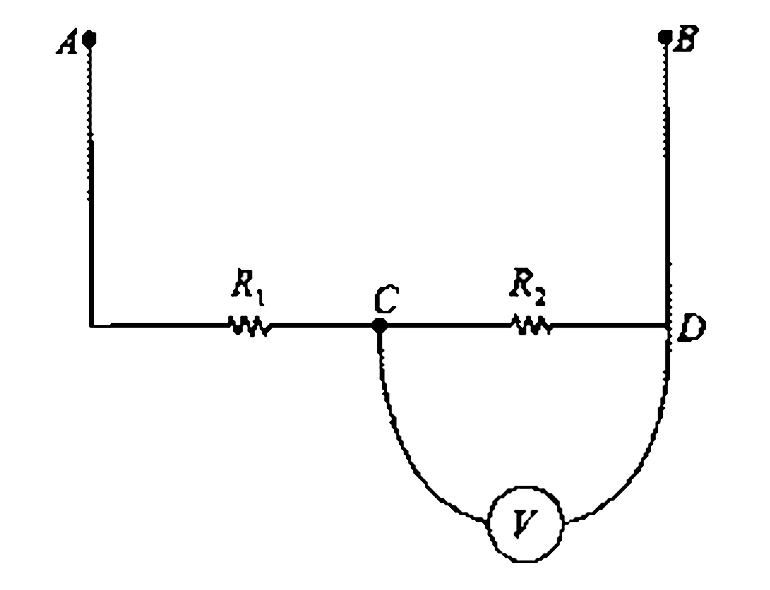
  3. Resistances R(1) and R(2), each 600 Omega, are connected in series as ...

    Text Solution

    |

  4. A moving coil galvanometer of resistance 20 Omega gives a full scale d...

    Text Solution

    |

  5. The resistance RG of the coil of a pivoted-coil galvanometer is 9.36 O...

    Text Solution

    |

  6. (a) A voltmeter with resistance Rv is connected across the terminals o...

    Text Solution

    |

  7. An ammeter with resistance RA is connected in series with a resistor R...

    Text Solution

    |

  8. Assume that the batteries in the circuit shown in figure- 3.384 have n...

    Text Solution

    |

  9. Three resistors having resistances of 1.60 Omega, 2.40 Omega and 4.80 ...

    Text Solution

    |

  10. Draw the circuit for experimental verification of Ohm's law using a so...

    Text Solution

    |

  11. A galvanometer (coil resistance 99 Omega.) is converted into an ammete...

    Text Solution

    |

  12. Two electic bulbs marked 25 W -220 V and 100 W - 220 V are connected i...

    Text Solution

    |

  13. Fig. illustrates a potentiometric circuit by means of which we can ve...

    Text Solution

    |

  14. A copper coil has resistance of 20.0 Omega at 0^@C and a resistance of...

    Text Solution

    |

  15. A metallic wire has a resistance of 120 Omega at 20^@C. Find the tempe...

    Text Solution

    |

  16. A galvanometer has coil resistance of 99 Omega with its full deflectio...

    Text Solution

    |

  17. A galvanometer has coil resistance 30 Omega and full deflection curren...

    Text Solution

    |

  18. In the circuit shown in figure-3.387, the voltmeter is having a resist...

    Text Solution

    |

  19. In the circuit shown in figure-3.388, each ammeter has coil resistance...

    Text Solution

    |

  20. In the circuit shown in figure-3 .3 89, the voltmeter reads 30V when i...

    Text Solution

    |