Home
Class 12
PHYSICS
A galvanometer (coil resistance 99 Omega...

A galvanometer (coil resistance `99 Omega`.) is converted into an ammeter using a shunt of `1 Omega` and connected as shown in figure (a). The ammeter reads `3 A`. The same galvanometer is convened into a voltmeter by connecting a resistance of `101 Omega` in series. This voltmeter is connected at, shown in figure (b). Its reading is found to be `4/5` of the full scale reading. Find :
(a) internal resistance r of the cell
(b) range of the ammeter and voltmeter
(c) full scale deflection current of the galvanometer.

Promotional Banner

Topper's Solved these Questions

  • CAPACITANCE

    PHYSICS GALAXY - ASHISH ARORA|Exercise UNSOLVED NUMERICAL PROBLEMS|40 Videos
  • ELECTROMAGNETIC INDUCTION AND ALTERNATING CURRENT

    PHYSICS GALAXY - ASHISH ARORA|Exercise Advance MCQs|33 Videos

Similar Questions

Explore conceptually related problems

A galvanometer can be converted into a voltmeter of certain range by connecting a resistance of 880Omega in series with it. When the resistance of 420Omega is connected in series, the range becomes half. Find the resistance of galvanometer.

Five 4 Omega resistance, 2 V battery and an ammeter are connected as shown in figure. Find the ammeter reading.

A voltmeter reading upto 10 V has a resistance of 1000 Omega . It can be converted into an ammeter reading up ot 10 A by connecting a shunt of

(a) Briefly explain how a galvanometer is converted into a voltmeter. (b) A voltmeter of a certain range is constructed by connecting a resistance of 90 Omega in series with a galvanometer. When the resistance of 470 Omega is connected in series, the range gets halved. Find the resistance of the galvanometer.

An ammeter A, a voltmeter V and a resistance R are connected as shown in the figure. If the voltmeter reading is 1.6V and the ammeter reading is 0.4 A, then R is

A galvanometer of resistance 50Omega is converted into an ammeter by connecting a low resistance (shunt) of value 1Omega in parallel to the galvanometer, S. If full - scale deflection current of the galvanometer is 10 mA, then the maximum current that can be measured by the ammeter is -

Five 4 Omega resistances, a 2 V battery and an ammeter are connected s shown in Fig. 4.43. Find the ammeter reading.

In the circuit shown, reading of the voltmeter connected across 400 Omega resistance is 60 V. If it is connected across 300 Omega resistance then reading in volt will be

PHYSICS GALAXY - ASHISH ARORA-CURRENT ELECTRICITY-All Questions
  1. Three resistors having resistances of 1.60 Omega, 2.40 Omega and 4.80 ...

    Text Solution

    |

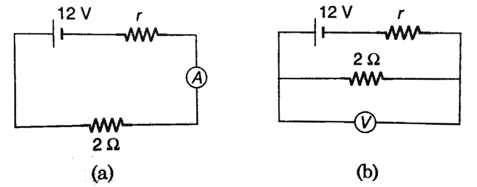
  2. Draw the circuit for experimental verification of Ohm's law using a so...

    Text Solution

    |

  3. A galvanometer (coil resistance 99 Omega.) is converted into an ammete...

    Text Solution

    |

  4. Two electic bulbs marked 25 W -220 V and 100 W - 220 V are connected i...

    Text Solution

    |

  5. Fig. illustrates a potentiometric circuit by means of which we can ve...

    Text Solution

    |

  6. A copper coil has resistance of 20.0 Omega at 0^@C and a resistance of...

    Text Solution

    |

  7. A metallic wire has a resistance of 120 Omega at 20^@C. Find the tempe...

    Text Solution

    |

  8. A galvanometer has coil resistance of 99 Omega with its full deflectio...

    Text Solution

    |

  9. A galvanometer has coil resistance 30 Omega and full deflection curren...

    Text Solution

    |

  10. In the circuit shown in figure-3.387, the voltmeter is having a resist...

    Text Solution

    |

  11. In the circuit shown in figure-3.388, each ammeter has coil resistance...

    Text Solution

    |

  12. In the circuit shown in figure-3 .3 89, the voltmeter reads 30V when i...

    Text Solution

    |

  13. A p.d of 220 V is maintained across a 12000 Omega rheostat as shown. T...

    Text Solution

    |

  14. Two electric bulbs, each designed to operate with a power of 500W in 2...

    Text Solution

    |

  15. Two resistors 400Omega and 800Omega are connected in series with a 6V ...

    Text Solution

    |

  16. In the circuit shown in figure-3.391, V(1) and V(2) are two voltmeters...

    Text Solution

    |

  17. A copper wire iis stretched to make it 0.1% longer. What is the percen...

    Text Solution

    |

  18. Three equal resistor connected in series across a source of enf toget...

    Text Solution

    |

  19. In the circuit shown in figure-3.392, find the power supplied by 10 V ...

    Text Solution

    |

  20. Calculate the charge on each capacitor and the potential difference ac...

    Text Solution

    |