Home
Class 12
PHYSICS
In the circuit shown in figure-3.387, th...

In the circuit shown in figure-3.387, the voltmeter is having a resistance `4000 Omega`. Find the percentage error in reading of this voltmeter.

Promotional Banner

Topper's Solved these Questions

  • CAPACITANCE

    PHYSICS GALAXY - ASHISH ARORA|Exercise UNSOLVED NUMERICAL PROBLEMS|40 Videos
  • ELECTROMAGNETIC INDUCTION AND ALTERNATING CURRENT

    PHYSICS GALAXY - ASHISH ARORA|Exercise Advance MCQs|33 Videos

Similar Questions

Explore conceptually related problems

In the circuit shown in the figure, the voltmeter reading is

In the circuit shown below. The reading of the voltmeter V is

Is correct. In the circuit shown in the figure, the voltmeter reading would be.

In the circuit shown, the reading of the voltmeter and the ammeter are

The emf of a battery is 6.0 V and its internal resistance is 1.5 Omega . Its potential differences is measured by a voltmeter of resistance 1000 Omega . Calculate the percentage error in the reading of emf shown by voltmeter.

In the circuit shown in figure-3.391, V_(1) and V_(2) are two voltmeters having resistances 6000 Omega and 4000 Omega respectively EMF of battery is 250V, having negligible internal resistance. Two resistances R_(1) and R_(2) are 4000 Omega and 6000 Omega respectively. Find the reading of the voltamter V_(1) and V_(2) when (a) Switch S is open ltbgt (b) Switch S is closed

In the circuit shown in figure-3 .3 89, the voltmeter reads 30V when it is connected across 400 Omega resistance. Calculate what the same voltmeter will read when it is connected across the 300 Omega resistance.

The emf of a battery is 4.0 V and its internal resistance is 1.5 Omega . Its potential difference is measured by a voltmeter of resistance 1000 Omega . Calculate the percentage error in the reading of emf shown by voltmeter.

PHYSICS GALAXY - ASHISH ARORA-CURRENT ELECTRICITY-All Questions
  1. A galvanometer has coil resistance of 99 Omega with its full deflectio...

    Text Solution

    |

  2. A galvanometer has coil resistance 30 Omega and full deflection curren...

    Text Solution

    |

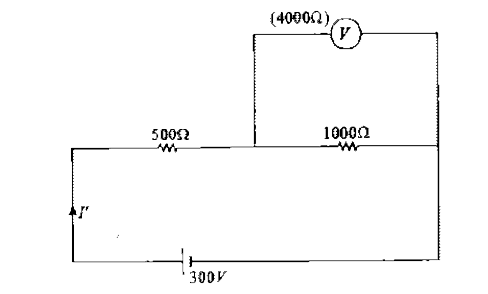
  3. In the circuit shown in figure-3.387, the voltmeter is having a resist...

    Text Solution

    |

  4. In the circuit shown in figure-3.388, each ammeter has coil resistance...

    Text Solution

    |

  5. In the circuit shown in figure-3 .3 89, the voltmeter reads 30V when i...

    Text Solution

    |

  6. A p.d of 220 V is maintained across a 12000 Omega rheostat as shown. T...

    Text Solution

    |

  7. Two electric bulbs, each designed to operate with a power of 500W in 2...

    Text Solution

    |

  8. Two resistors 400Omega and 800Omega are connected in series with a 6V ...

    Text Solution

    |

  9. In the circuit shown in figure-3.391, V(1) and V(2) are two voltmeters...

    Text Solution

    |

  10. A copper wire iis stretched to make it 0.1% longer. What is the percen...

    Text Solution

    |

  11. Three equal resistor connected in series across a source of enf toget...

    Text Solution

    |

  12. In the circuit shown in figure-3.392, find the power supplied by 10 V ...

    Text Solution

    |

  13. Calculate the charge on each capacitor and the potential difference ac...

    Text Solution

    |

  14. Calculate the potential of point A in the circuits shown in figure-3.3...

    Text Solution

    |

  15. In the circuit shown in figure-3.395, find the charges on capacitors o...

    Text Solution

    |

  16. A capacitor of capacitance C has potential difference E/2 and another ...

    Text Solution

    |

  17. Initially, the switch is in position 1 for a long time. At t = 0, the ...

    Text Solution

    |

  18. A charged capacitor C1 is discharged through a resistance R by putting...

    Text Solution

    |

  19. A capacitor with capacitance C = 400 pF is connected via a resistance ...

    Text Solution

    |

  20. The capacitors are initially uncharged. In a certain time the capacito...

    Text Solution

    |