A
B
C
D

Text Solution
Verified by Experts
The correct Answer is:


Topper's Solved these Questions
Similar Questions
Explore conceptually related problems
D MUKHERJEE-IIT QUESTIONS 4-Integer type
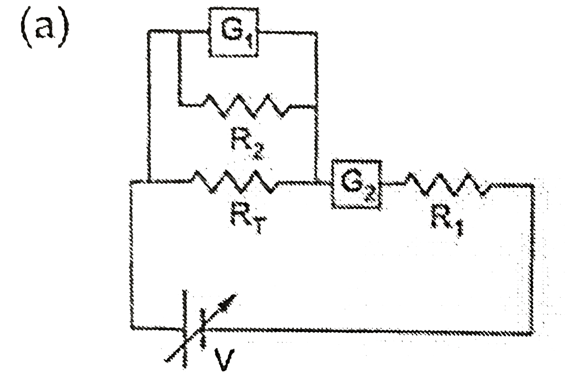
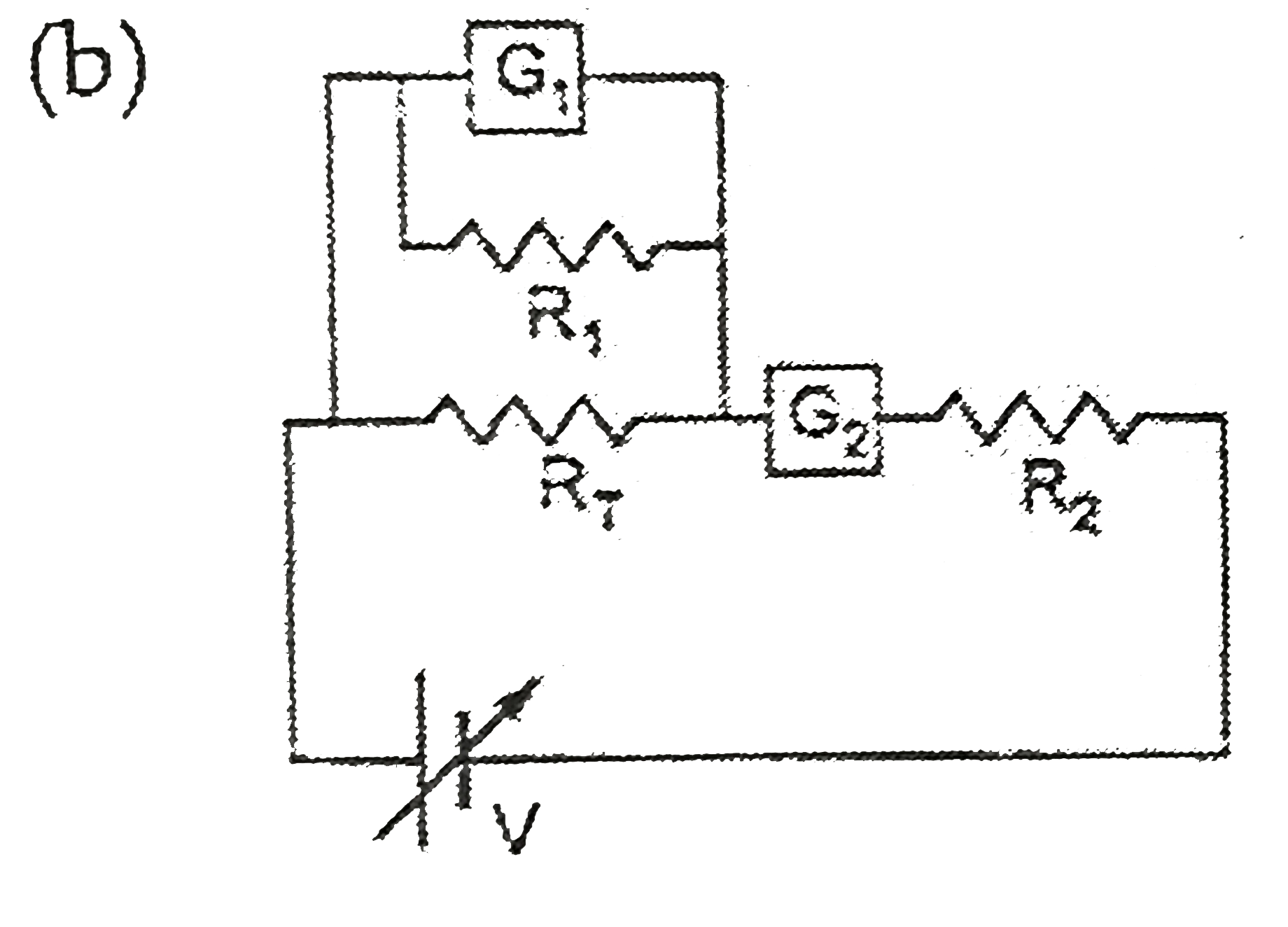
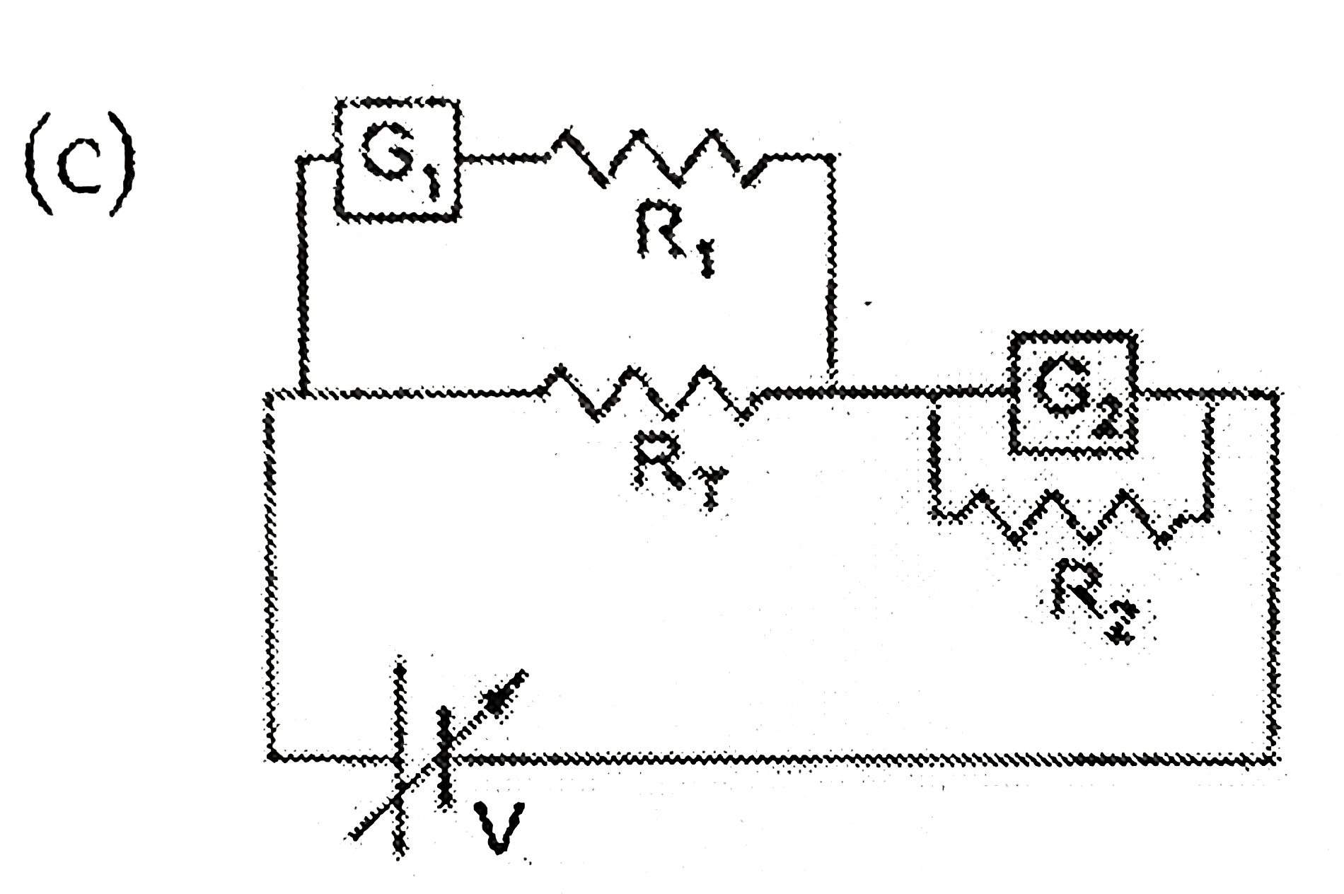
- To verify Ohm's law, a student is provided with a test resistor RT, a ...
Text Solution
|
- When two progressive waves y(1) = 4 sin (2x - 6t) and y(2) = 3 sin (2x...
Text Solution
|
- A 0.1 kg mass is suspended from a wire of negligible mass. The length...
Text Solution
|
- A binary star consists of two stars A(mass 2.2 Ms) and B (mass 11 Ms)...
Text Solution
|
- Graviational acceleration on the surface of plane fo (sqrt6)/(11)g. wh...
Text Solution
|
- A piece of ice (heat capacity =2100 J kg^(-1) .^(@)C^(-1) and latent h...
Text Solution
|
- A stationary source is emitting sound at a fixed frequency f(0), which...
Text Solution
|
- The focal length of thin biconvex lens is 20 cm. When an object is mov...
Text Solution
|
- A proton and an alpha-particle are accelerated, using the same potenti...
Text Solution
|
- When two identical batteries of internal resistance 1Omega each are co...
Text Solution
|
- Two spherical bodies A (radius 6cm) and B (radius 18cm) are at tempera...
Text Solution
|