Home
Class 12
PHYSICS
Fig 14.18 shows a series LCR circuit con...

Fig 14.18 shows a series LCR circuit connected to a variable frequency 200 V source:
`L=4.0H, C=100 muF` and `R=40 Omega`.
(i) Calculate the resonant frequency of the circuit.
(ii) Obtain the impedance of the circuit and the amplitude of the current at resonating frequency.
(iii) Determine r.m.s. potential drop across L.

Promotional Banner

Topper's Solved these Questions

  • AC CIRCUITS AND ELECTRIC CIRCUITS

    SL ARORA|Exercise problem|57 Videos
  • ATOMS, NUCLEI AND MOLECULES

    SL ARORA|Exercise Problems For Self Practice|87 Videos

Similar Questions

Explore conceptually related problems

Figure here, shows a series L-C-R circuit connected to a variable frequency 230 V source. L = 5.0H, C = 80 muF and r = 40 Omega (a) Determine the source frequency which drives the circuit in resonance. (b) Obtain the impedance of the circuit and the amplitude of current at the resonating frequency. (c) Determine the rms potential drops across the three elements of the circuit. show that the potential drop across the L-C combination is zero at the resonating frequency.

A series LCR circuit connected to a variable frequency 230 V source has L = 5.0 H, C = 80 mu F , R = 40 Omega , Fig. (a) Determine the source frequency which drives the circuit in resonance. (b) Obtain the impedance of the circuit and amplitude of current at at resonating frequency. (c ) Determine the r.m.s. potential drops acorss the three elements the circuits. Show that the potential drop acorss the LC combination is zero at the resonating frequecny.

A variable frequency 230 V alternating voltage source is connected across a series combination of L = 5.0 H, C = 80 mu F and R = 40 Omega (i) Calculate the angurla frequency fo the source which drives the circuitin resonance. (ii) Obtain r.m.s. the impedance of the circuit and amplitude of current at resonance frequency (iii) Obtain r.m.s. potential drop across the three elements of the circuit at resonating frequency. (iv) How do you explain the observation that the algerbraic sum of voltages across the three elements obtained is greater than the supplied voltage.

Figure shows a series LCR circuit connected to a variable frequency 230 V source. The source frequency which drives the circuit the circuit in resonance is

An LCR series circuit contains L = 8 H, C = 0.5 muF and R =100 Omega The resonant frequency of the circuit is .

The figure shows a series LCR circuit with L=10.0 H_(2), C=40 mu F, R=60 Omega connected to a variable frequency 240 V source. Calculate (i) The angular frequency of the source which drives the circuit at resonance. (ii) The current at the resonating frequency. (iii) The rms potential drop across the capacitor at resonance.

In the given figure , a series L-C-R circuit is connected to a variable frequency source of 230 V . The impedance and amplitude of the current at the resonating frequency will be

Fig. shows series LCR circuit with L = 5.0 H, C = 80 mu F, R = 40 Omega connected to a variable frequency 240 V source. Calculate (i) the angular freuquency of the source which drives the circuit at resonance. (ii) Current at the resonanting frequency. (iii) the rms pot. drop across the capacitor at resonance.

A series LCR circuit with L = 4.0 h, C = 100 mu F and R = 60 Omega is connected to a varialbe frequency 240 V source. Calcalate (i) angular frequency of the source which drives the circuit in resonace, (ii) current at the resonating frequency, (iii) rms potential drop across the inductro at resonance.

In a series L-C-R circuit shown in the figure , what is the resonance frequency and the current at the resonating frequency?

SL ARORA-AC CIRCUITS AND ELECTRIC CIRCUITS-problem
  1. An a,c, source of frequency 50 hertz is connected to a 50 mH inductor ...

    Text Solution

    |

  2. A 200km long telegraph wire has capacitance of 0.014 mu F//km If it ca...

    Text Solution

    |

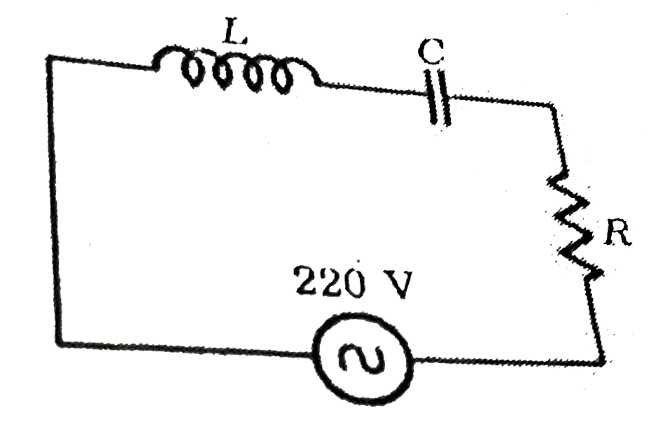
  3. Fig 14.18 shows a series LCR circuit connected to a variable frequency...

    Text Solution

    |

  4. A 100 mH inductor, a 20 muF capacitor and a 10 ohm resistor are connec...

    Text Solution

    |

  5. Compute the resonant frequency and the Q factor of a series LCR circui...

    Text Solution

    |

  6. In the circuit shown in fig. potential diff. across L, C and and R are...

    Text Solution

    |

  7. A 60 cycle AC circuit has a resistance of 200 Omega and inductance of ...

    Text Solution

    |

  8. A transformer has 300 primary turns and 2400 secondary turns: If the p...

    Text Solution

    |

  9. A transformer has 200 primary turns and 150 secondary turns. If the op...

    Text Solution

    |

  10. The turns ratio of a transformer is 12.5. If its primary is connected ...

    Text Solution

    |

  11. A step-up transfomer operates on a 220 volt line and supplies to load,...

    Text Solution

    |

  12. In a stepup transformer, the ratio of number of turns in primary and s...

    Text Solution

    |

  13. Calculate current drawn by primary coil of a transformer, Which steps ...

    Text Solution

    |

  14. The output voltage of an ideal transformer, connected to a 240 V ac. w...

    Text Solution

    |

  15. A step down transformer is used at 220 V to provide a current of 0.5 A...

    Text Solution

    |

  16. A step down transformer converts transmission line voltage from 2200 V...

    Text Solution

    |

  17. The number of turns in the primary and secondary coils of an ideal tra...

    Text Solution

    |

  18. The primary of a transformer has 200 turns and secondary has 1000 turn...

    Text Solution

    |

  19. An a.c generator consists of a coil of 50 turns and area 2.5 m^(2) rot...

    Text Solution

    |

  20. A generator develops an e.m.f. of 120 V and has a terminal potential d...

    Text Solution

    |