Home
Class 12
PHYSICS
In the circuit shown in the figure , if ...

In the circuit shown in the figure , if a conducting wire is conneted between point A and B , thent the current in the wire AB will

A

Be from A to B

B

Be from B to A

C

Not flow

D

Direction of current will be decided by magnitude of source voltage

Text Solution

Verified by Experts

The correct Answer is:
A

Use voltage divider law

From the voltage divider law
`V_A = 2/3 xxV =(2V)/(3)`
`V_B = 2/6V = V/3`
Here `V_A gt V_B`
Hence, current in wire will flow from A to B
Promotional Banner

Topper's Solved these Questions

  • MAJOR TEST 9

    NEET MAJOR TEST (COACHING)|Exercise PHYSICS|44 Videos
  • NEET DRILL 3

    NEET MAJOR TEST (COACHING)|Exercise PHYSICS|45 Videos

Similar Questions

Explore conceptually related problems

In the circuit shown if a conducting wire is connected between points A and B, the current in this wire will :-

In the circuit of a condacting wire is connected between point A and B the current is this wire will

In the following circuit, a conducing wire is connected between the terminals B and D, the current in the wire will

In the circuit shown, if a wire is connected between points A and B. How much current will flow through that wire?

In the circuit shown in figure -3.113 Find potential difference between the point A and B and the currents though each branch.

Shown in the figure . Find out the current in the wire BD

In the given network, if the points B and D are connected by a copper wire, then the current in the wire will

In the circuit shown in figure resistance of each wire is r. Net resistance across

An irregular loop of conducting wire is lying on a frictionless table as shown in the figure. The wire is clamped at points a and k, when a current i is passed thorugh it, then the wire will

NEET MAJOR TEST (COACHING)-NEET 2020 TEST 5-PHYSICS
  1. For the given conductor the drift speed of electrons at cross section ...

    Text Solution

    |

  2. The value of R in the circuit shown in the figure is

    Text Solution

    |

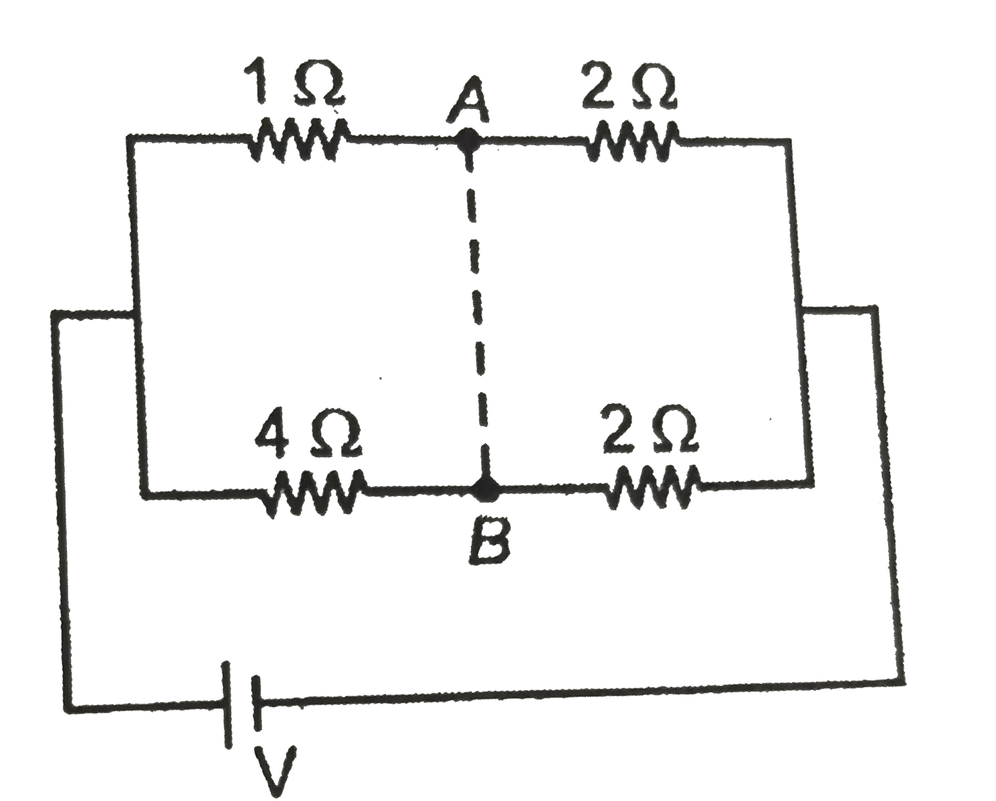
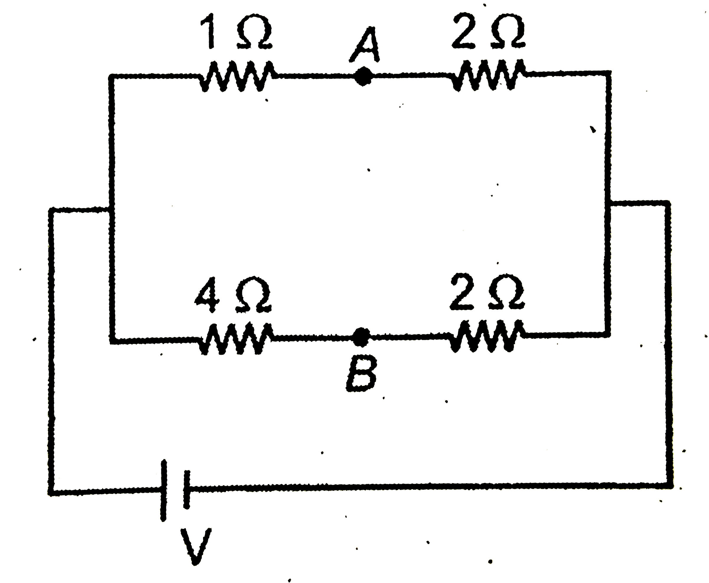
  3. In the circuit shown in the figure , if a conducting wire is conneted ...

    Text Solution

    |

  4. Consider the following statements: Statement (I) : Kirchoff's juctio...

    Text Solution

    |

  5. A condcuting slab of thickness d/2 is inserted between the plates of p...

    Text Solution

    |

  6. For the arrangement shown in the figure, the charge on the 4muF capac...

    Text Solution

    |

  7. Five capacitors each of capacitance C and breakdown voltage V are conn...

    Text Solution

    |

  8. Eight capacitors , each of capacitance 2muF are conneted as shown in t...

    Text Solution

    |

  9. An electric dipole moment p is aligned parallel to a uniform electric ...

    Text Solution

    |

  10. Five capacitors are connected in series as shown in figure with a batt...

    Text Solution

    |

  11. Two point charge qA " and " qB are placed in a uniform external electr...

    Text Solution

    |

  12. A large number of particles each having electric charge 1muC are place...

    Text Solution

    |

  13. Figure shows the variation of electric field intensity E with distance...

    Text Solution

    |

  14. Figure shows a set of equipotential surfaces. The magnitude and direct...

    Text Solution

    |

  15. The electric potential at a point (x, y, z) is given by V=-xy+z-z^3yx ...

    Text Solution

    |

  16. Two point charges +q and -q are placed at point A and B respectively w...

    Text Solution

    |

  17. A, B and C are three points in an electrostatics field. The electric p...

    Text Solution

    |

  18. Three point charges are placed as shown in the figure. S is a gaussian...

    Text Solution

    |

  19. A very long uniformly charged thin wire whose one end is at point (0,...

    Text Solution

    |

  20. Three point charges 1muC ,1muC " and " -2muC are placed at points havi...

    Text Solution

    |