Home
Class 12
PHYSICS
For the circuit A and B as shown in the ...

For the circuit A and B as shown in the figure, identify the correct option.

A

Circuit A is for accurate measurement of high resistance and B is for low resistance.

B

Circuit A is for accurate measurement of low resistance and B is for high resistance.

C

Both circuit can accurately measured high resistance only.

D

Both circuits can accurately measured low resistance only

Text Solution

Verified by Experts

The correct Answer is:
B

In the given circuits, A represents an ammeter, which is used to measured the current passing through the resistor it is not a low resistive device, so that it does not affect the circuit. It is connected in series with resistor.
Similarly, V represents a voltmeter, which is used to measure the potential drop across the resistor It is usually a high resistive device, so that the negaligible current passes through it. Thus, does not affect no current passing through the resistor. It is connected in parallel with to the resistor, This implies that, these devices are used measure.
current and voltage drop across a resistor, without actually affecting any of these quantities because of thire addition in the circuit.
So, the given circuits A and B as shown below,

We can conclud that the circuit A has been correctly connected. Therefore, it can be used to measure R accurately, which can be calculated with the help of ammeter and voltmeter reading as,
`R=("voltage (V)")/("Current (I)")` [From ohm's law]
However, when the arrangement of ammeter and voltameter is as per given in Circuit B. The circuit then is usually used for measuring higher resistance as compare to circuit A.
Promotional Banner

Topper's Solved these Questions

  • TS EAMCET 2018 (7 MAY SHIFT 1)

    TS EAMCET PREVIOUS YEAR PAPERS|Exercise PHYSICS|40 Videos
  • TS EAMCET 2019 (3 MAY SHIFT 2)

    TS EAMCET PREVIOUS YEAR PAPERS|Exercise PHYSICS|40 Videos

Similar Questions

Explore conceptually related problems

Identify the figures and select the correct option .

In the circuit shown in the figure, the current 'I' is

Look at the picture given below. What kind of change is shown in the picture? Choose the correct option.

Observe the following diagram and identify the correct option

Identify the figures A and B and select the correct option .

Identify the instrument shown in the fig.

TS EAMCET PREVIOUS YEAR PAPERS-TS EAMCET 2019 (3 MAY SHIFT 1)-Physics
  1. Standing waves are produced in a string 16 m long. If there are 9 node...

    Text Solution

    |

  2. A highway truck has two horns A and B. When sounded together, the driv...

    Text Solution

    |

  3. When light of an unknown polarisation is examined with a polaroid, it ...

    Text Solution

    |

  4. In a Young's double slit experiment, mth order and nth order of bright...

    Text Solution

    |

  5. Two small conductiong ball of identical mass 20 g and identical charge...

    Text Solution

    |

  6. The space between the two large parallel plates is filled with a mater...

    Text Solution

    |

  7. Identify the correct statement among the following.

    Text Solution

    |

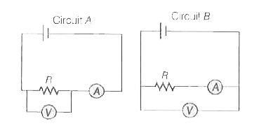
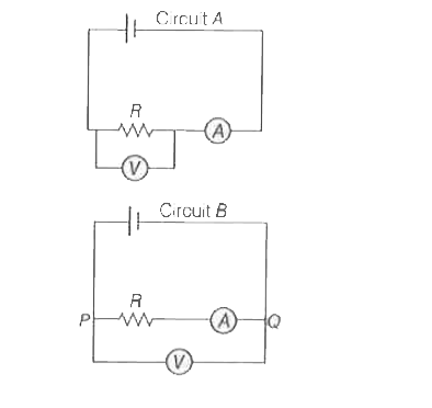
  8. For the circuit A and B as shown in the figure, identify the correct o...

    Text Solution

    |

  9. Two infinitely long straight wires A and B, each carrying current I ar...

    Text Solution

    |

  10. A long straight wire carrying current 16 A is bent at 90^(@) such that...

    Text Solution

    |

  11. The magnitude of the force vector acting on a unit length of a thin wi...

    Text Solution

    |

  12. A 10 Omega coil of 180 turns and diameter 4 cm is placed in a uniform ...

    Text Solution

    |

  13. An inductor coil is connected to a capacitor and an AC source of rms v...

    Text Solution

    |

  14. An electromagnetic wave of frequency 3.0 MHz passes from vacuum into a...

    Text Solution

    |

  15. A particle of charge q, mass m and energy E has de-Broglie wavelength ...

    Text Solution

    |

  16. The collision of an electron with kinetic energy 5.5 eV and a hydrogen...

    Text Solution

    |

  17. An alloy is composed of two radiactive materials A and B having equal ...

    Text Solution

    |

  18. When a zener diode is used as a regulator with zener voltage of 10 V, ...

    Text Solution

    |

  19. The logic circuit below has the truth table, same as that of

    Text Solution

    |

  20. A message signal is used to modulate a carrier frequency. If the peak ...

    Text Solution

    |