Home
Class 12
PHYSICS
Consider a box with three terminals on t...

Consider a box with three terminals on top of it as shown in figure.

Three components namely, two germanium diodes and one resistor are connected across these three terminals in some arrangement
A student performs an experiment in which any two of these three terminals are connected in the circuit shown in figure.
The student obtains graphs of current-voltage characteristics for unknown combination of components between the two terminals connected in the circuit. The graphs are
(i) When A is positive and B is negative

(ii) When A is negative and B is positive

(iii) When B is negative and C is positve

(iv) When B is positive and C is neagtive

(v) When A is positive and C is negative

(vi) When A is negative and C is positive

From these graphs of current `-` voltage characteristic shown in fig. (c) to (h) determine the arrangement of components between A, B and C.

Text Solution

Verified by Experts

(a) In `V - I` graph of condition (i), a reverse characteristics is shown in fig. (c). Here A is connected to `n-`side of `p - n` junction I and B is connected to `p-`side of `p - n` junction `I` with a resistance in series.
(b) In `V - I` graph of condition (ii), a forward characteristics is shown in fig. (d), where `0.7 V` is the knee voltage of `p - n` junction `11//`slope `= (1//1000) Omega`.
It means A is connected to `n-` side of `p - n` junction I and B is connected to `p-`side of `p - n` junction I and resistance R is in series of `p - n` junction I between A and B.
(c) In `V = I` graph of condition (iii), a forward characteristics is shown in figure (e), where `0.7V` is the knee voltage. In this case `p-`side of `p - n` junction `II` is connected to C and `n-`side of `p - n` junction `II` to B.
(d) In `V - I` graphs of conditions, (iv), (v), (vi) also concludes the above connection of `p - n` junction `I" and " II` along with a resistance R.
Thus, the arrangement of `p - n I, p - n II` and resistance R between A, B and C will be as shown in the figure.
Promotional Banner

Topper's Solved these Questions

  • MOVING CHARNGES AND MAGNETISM

    NCERT EXEMPLAR|Exercise Moving Charnges And Magnetism|29 Videos
  • RAY OPTICS AND OPTICAL INSTRUMENTS

    NCERT EXEMPLAR|Exercise Ray Optics And Optical Instruments|32 Videos

Similar Questions

Explore conceptually related problems

Find the equivalent resistances across terminals A and B in the circuit shown in figure-3.38.

Potential different across the terminals of the battery shown in figure is

Find equivalent resistant across terminals A and B in the circuit shown in figure-3.30.

Three bulbs A, B, C are connected in a circuit as shown in Figure 14.2. When the switch is ‘ON’

Three inductances are connected as shown in figure. Calculate the resultant inductance.

Find the equivalent capacitance across terminals A and B in the circuit shown in figure.

NCERT EXEMPLAR-NUCLEI-Nuclei
  1. The amplifiers X, Y and Z are connected in series. If the voltage gain...

    Text Solution

    |

  2. In a CE transistor amplifier, there is a current and voltage gain asso...

    Text Solution

    |

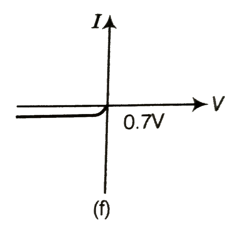
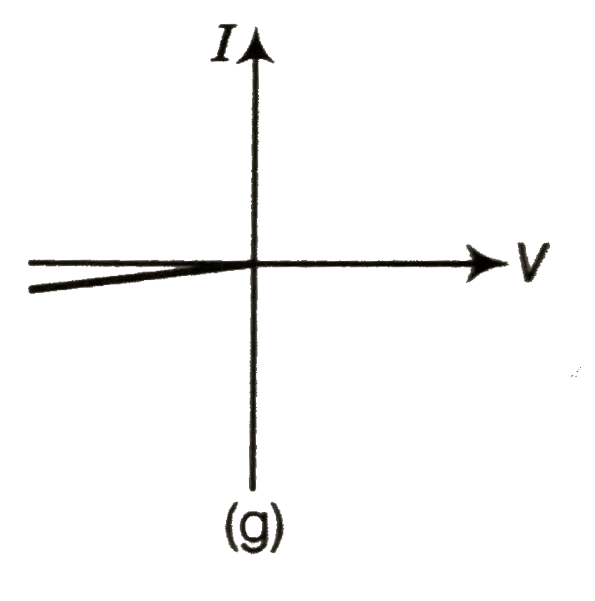
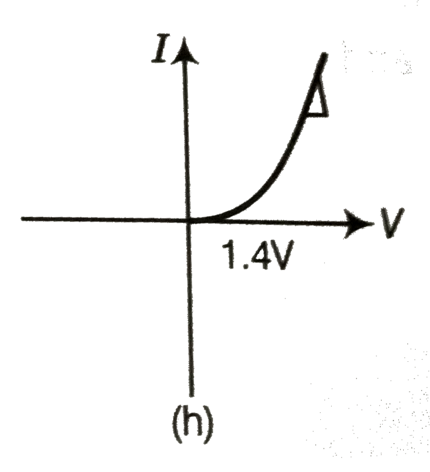
  3. (i) Name the type of a diode whose characteristics are shown in figure...

    Text Solution

    |

  4. Three photodiodes D1 , D2 and D3 are made of semiconductors having ...

    Text Solution

    |

  5. If the resistance R(1) is increased (see figure), how will the reading...

    Text Solution

    |

  6. Two car garages have a common gate which needs to open automatically w...

    Text Solution

    |

  7. How would you set up a circuit to obtain NOT gate using a transistor?

    Text Solution

    |

  8. Explain why elemental semiconductor cannot be used to make visible LED...

    Text Solution

    |

  9. Write the truth table for the circuit shown in figure given below. Nam...

    Text Solution

    |

  10. A Zener of power rating 1 W is to be used as a voltage regulator. If Z...

    Text Solution

    |

  11. If each diode in figure has a forward has a forward bias resistance of...

    Text Solution

    |

  12. In the circuit shown in Fig. when the input voltage of the base resist...

    Text Solution

    |

  13. Draw the output signals C(1) " and " C(2) in the given combination of ...

    Text Solution

    |

  14. Consider the circuit arrangnent shown in Fig. for studying input and o...

    Text Solution

    |

  15. Assuming the ideal diode, draw the output waveform for the circuit giv...

    Text Solution

    |

  16. Suppose a 'n'- type wafer is created by doping Si crystal having 5xx10...

    Text Solution

    |

  17. An X-OR gate has following truth table: It is represented by followi...

    Text Solution

    |

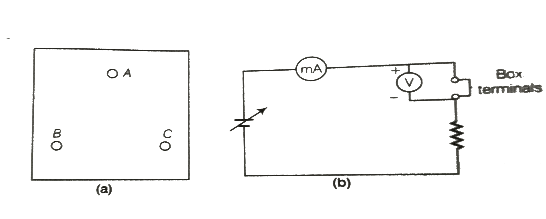
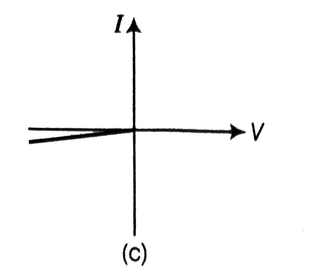
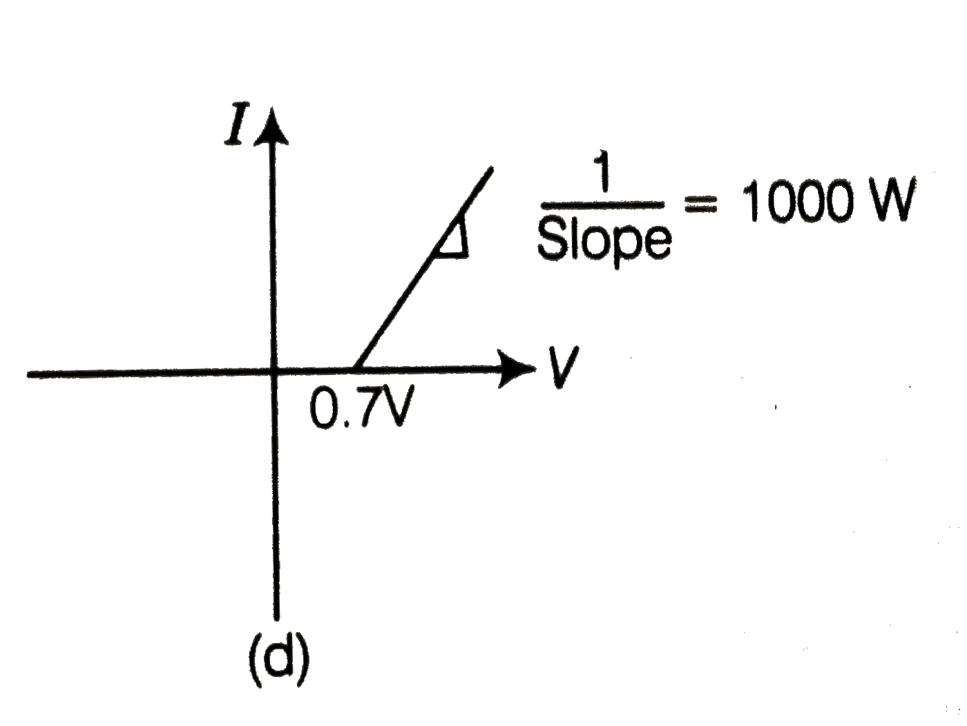
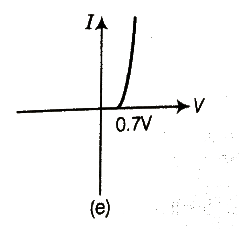
  18. Consider a box with three terminals on top of it as shown in figure. ...

    Text Solution

    |

  19. For the transistor circuit shown in figure , evaluate VE , RB and RE. ...

    Text Solution

    |

  20. In the circuit shown in fig. (a), final the value of R(C).

    Text Solution

    |