A
B
C
D
Text Solution
Verified by Experts
The correct Answer is:


Topper's Solved these Questions
SEMICONDUCTOR ELECTRONICS
NARAYNA|Exercise EXERCISE -2 (H.W) (APPLICATIONS OF JUNCTION DIODE AS RECTIFIER)|4 VideosSEMICONDUCTOR ELECTRONICS
NARAYNA|Exercise EXERCISE -2 (H.W) (TRANSISTORS)|9 VideosSEMICONDUCTOR ELECTRONICS
NARAYNA|Exercise EXERCISE -2 (H.W) (INTRINSIC, EXTRINSIC SEMICONDUCTORS)|6 VideosSEMI CONDUCTOR DEVICES
NARAYNA|Exercise Level-II (H.W)|36 VideosWAVE OPTICS
NARAYNA|Exercise Exercise - 4 Polarisation|9 Videos
Similar Questions
Explore conceptually related problems
NARAYNA-SEMICONDUCTOR ELECTRONICS-EXERCISE -2 (H.W) (JUNCTION DIODES)
- The width of depletion region in p-n junction diode is 500 nm and an i...
Text Solution
|
- A p-n junction has acceptor impurity concentration of 10^(17) cm^(-3) ...
Text Solution
|
- A p-n junction diode when forward baiased has a drop of 0.5 V which is...
Text Solution
|
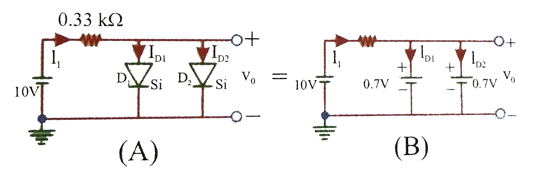
- In the circuit shown in figure (1), the V(0),I(1),I(D(1)), and I(D(3))...
Text Solution
|
- For a junction diode, the ratio of forward current (I(f)) and reverse ...
Text Solution
|