A
B
C
D

Text Solution
Verified by Experts
The correct Answer is:


Topper's Solved these Questions
SEMICONDUCTOR ELECTRONICS
NARAYNA|Exercise EXERCISE -3|43 VideosSEMICONDUCTOR ELECTRONICS
NARAYNA|Exercise EXERCISE-4|35 VideosSEMICONDUCTOR ELECTRONICS
NARAYNA|Exercise EXERCISE -2 (H.W) (TRANSISTORS)|9 VideosSEMI CONDUCTOR DEVICES
NARAYNA|Exercise Level-II (H.W)|36 VideosWAVE OPTICS
NARAYNA|Exercise Exercise - 4 Polarisation|9 Videos
Similar Questions
Explore conceptually related problems
NARAYNA-SEMICONDUCTOR ELECTRONICS-EXERCISE -2 (H.W) (LOGIC GATE)
- The following configuration of gates is equivalent to
Text Solution
|
- The combination of the gates shown below produces
Text Solution
|
- Which of the following truth tables is true?
Text Solution
|
- Truth table for system of four NAND gates as shown in figure is
Text Solution
|
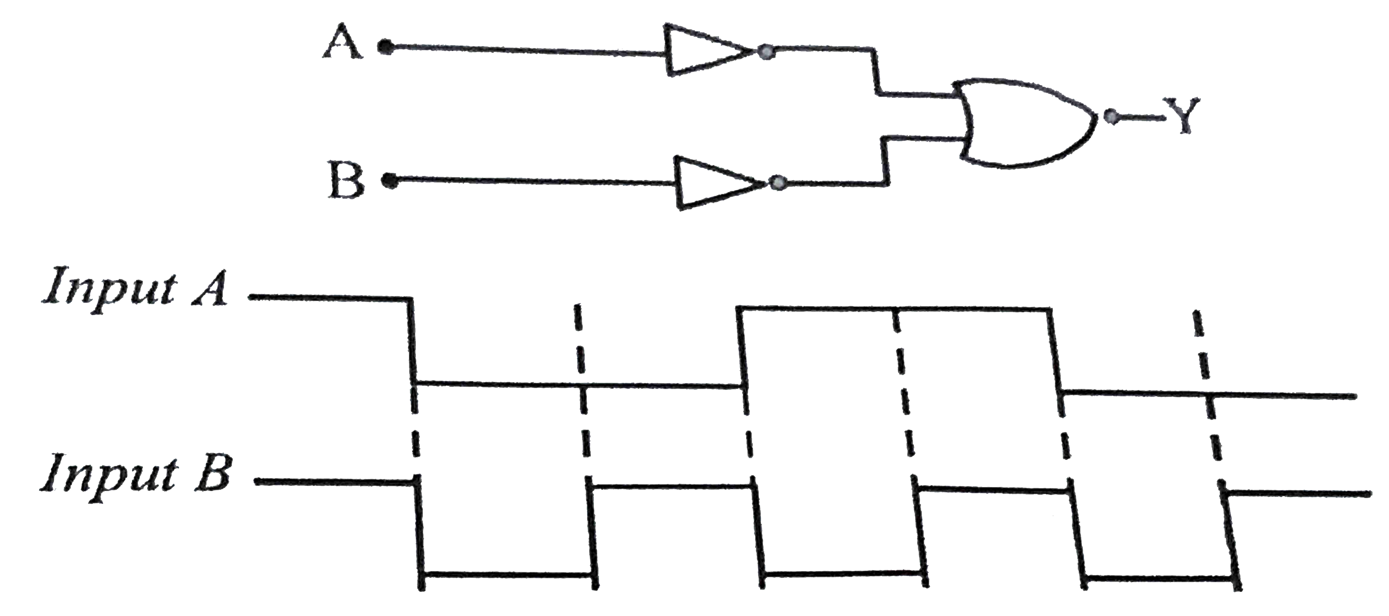
- The logic circuit shown below has the input waveforms ‘A’ and ‘B’ as s...
Text Solution
|
- Logic gates X and Y have the truth tables shown below When the ou...
Text Solution
|