Home
Class 12
PHYSICS
An inductor of inductance L = 400 mH and...

An inductor of inductance L = 400 mH and resistors of resistance `R_(1) = 2Omega` and `R_(2) = 2Omega` are connected to a battery of emf 12 V as shown in the figure. The internal resistance of the battery is negligible. The switch S is closed at `t = 0`. The potential drop across L as a function of time is

A

`12/te^(-31) V`

B

`6(1-e^(-t//0.2))V`

C

`12 e^(-5t)V`

D

`5 e^(-5t)V`

Text Solution

Verified by Experts

The correct Answer is:
C

`V_(L)=epsilone-(R_(2)t)/L=12.e-(2t)/(400xx10^(-3))=12 e^(-5t)`
Promotional Banner

Topper's Solved these Questions

  • ELECTROMAGNETIC INDUCTION

    RESONANCE|Exercise Exercis-3 PART 3|16 Videos
  • ELECTROMAGNETIC INDUCTION

    RESONANCE|Exercise A.l.P|19 Videos
  • ELECTROMAGNETIC INDUCTION

    RESONANCE|Exercise Exercis-3 PART 1|18 Videos
  • ELECTRODYNAMICS

    RESONANCE|Exercise Advanced level problems|31 Videos
  • ELECTROSTATICS

    RESONANCE|Exercise HLP|39 Videos

Similar Questions

Explore conceptually related problems

An inductor of inductance L=400 mH and resistor of resistance R_(1) = 2(Omega) and R_(2) = 2 (Omega) are connected to a battery of emf E = 12 Vas shown in the figure. The internal resistance of the battery is negligible. The switch S is closed at time t =0. What is the potential drop across L as a function of time? After the steady state is reached, the switch is opened. What is the direction and the magnitude of current through R_(1) as a function of time?

An inductor of inductance L=400 mH and resistors of resistances R_1=2Omega and R_2=2Omega are connected to a battery of emf E=12 V as shown in the figure. The internal resistance of the battery is negligible. The switch S is closed at time t=0 . What is the potential dro across L s a function of time? After the steady state is reached, the switch is opened. What is the direction ad the magnitude of current throough R_1 as a function of time?

An inductor of self-inductance L and resistor of resistance R are connected in series to a battery of emf E and negligible resistance.Calculate the maximum rate at which energy is stored in the inductor.

A 4 m long wire of resistance 8Omega is connected in series with a battery of emf 2V and a resistor of 7Omega . The internal resistance of the battery is 1Omega . What is the potential gradient along the wire ?

A 4mu F capacitor is connected to a battery of emf 24V. Through a resistance of 5 M Omega and a switch which is kept open initially. Internal resistance of the battery is negligible. Switch is closed at t=0. Potential difference across capacitor and resistor at t=0 are respectively.

An inductor of inductance L and another resistor of resistance R are connected in series with a battery of emf E and a switch. Switch is closed at t = 0. How much charge will pass through the battery in one time constant? Internal resistance of the battery is negligible.

Shows a network of eight resistors battery of resistance R(= 2 Omega) connected in a 3V battery of negligible internal resistance. The current I in the circuit is

Two sources of emf 6 V and internal resistance 3 Omega and 2 Omega are connected to anexternal resistance R as shown. If potential difference across battery A is zero, then the value of R is

A 5 V battery with internal resistance 2Omega and a 2V battery with internal resistance 1Omega are connected to a 10Omega as shown in the figure. The current in the 10Omega resistance is

Two resistors of resistances 2Omega and 6Omega are connected in parallel. This combination is then connected to a battery of emf 2 V and internal resistance 0.5 Omega . What is the current flowing thrpough the battery ?

RESONANCE-ELECTROMAGNETIC INDUCTION-Exercis-3 PART 2
  1. One conducting U tube can slide inside another as shown in figure, mai...

    Text Solution

    |

  2. A coil of inductance 300mh and resistance 2Omega is connected to a sou...

    Text Solution

    |

  3. An inductor (L = 100 mH), a resistor (R = 100 (Omega)) and a battery (...

    Text Solution

    |

  4. Two coaxial solenoids are made by winding thin insulated wire over a p...

    Text Solution

    |

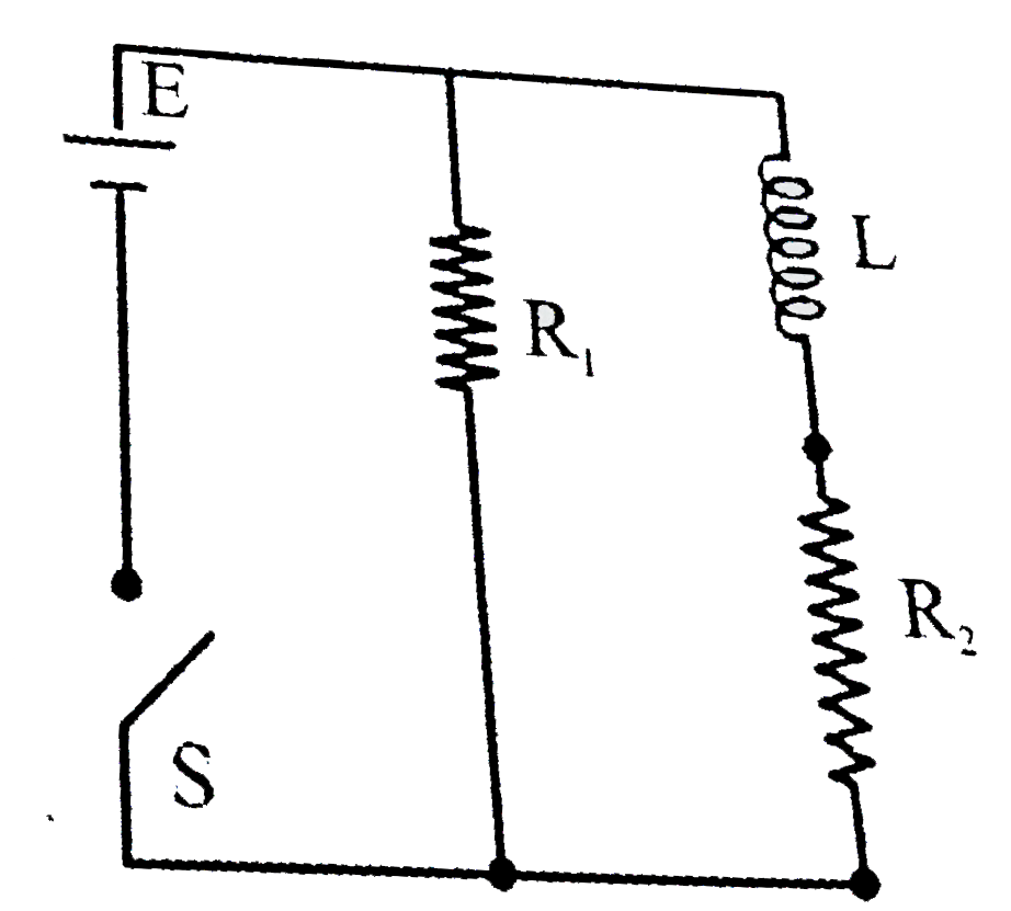
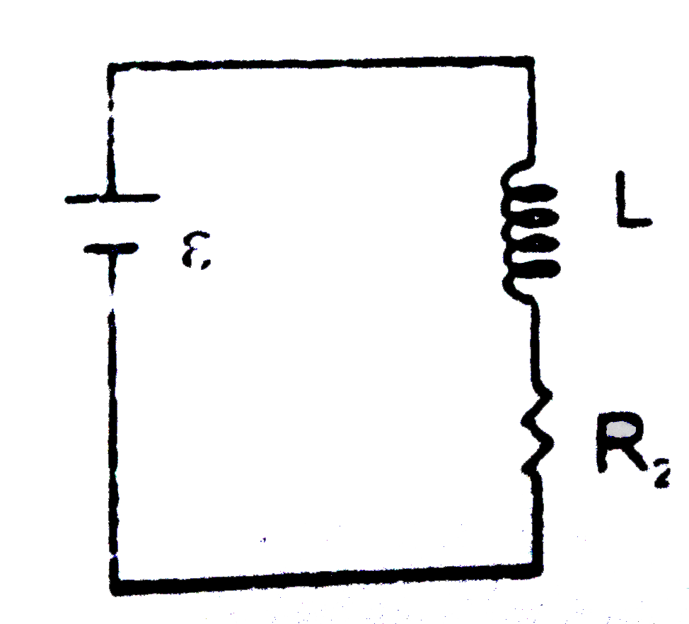
  5. An inductor of inductance L = 400 mH and resistors of resistance R(1) ...

    Text Solution

    |

  6. A rectangular loop has a sliding connector PQ of length l and resistan...

    Text Solution

    |

  7. A fully charged capacitor C with initial charge q(0) is connected to a...

    Text Solution

    |

  8. A boat is moving due east in a region where the earth's magnetic field...

    Text Solution

    |

  9. A horizontal straight wire 20 m long extending from east to west falli...

    Text Solution

    |

  10. A coil is suspended in a uniform magnetic field, with the plane of the...

    Text Solution

    |

  11. A metallic rod of length 'l' is tied to a string of length 2l and made...

    Text Solution

    |

  12. A circular loop of radius 0.3 cm lies parallel to amuch bigger circula...

    Text Solution

    |

  13. In an LCR circuit as shown below both switches are open initially. Now...

    Text Solution

    |

  14. In the circuit shown here, the point 'C' is kept connected to point 'A...

    Text Solution

    |

  15. An inductor (L =0.03 H) and a resistor (R = 0.15k(Omega)) are connecte...

    Text Solution

    |

  16. An LCR curcuit is equivalent to a damped pendulum. In an LCR circuit t...

    Text Solution

    |