A
B
C
D
Text Solution
Verified by Experts
The correct Answer is:


Topper's Solved these Questions
Similar Questions
Explore conceptually related problems
RESONANCE-CAPACITANCE-Exercise - 2
- The potential difference between the points P and Q in the adjoining c...
Text Solution
|
- The time constant of the circuit shown is :
Text Solution
|
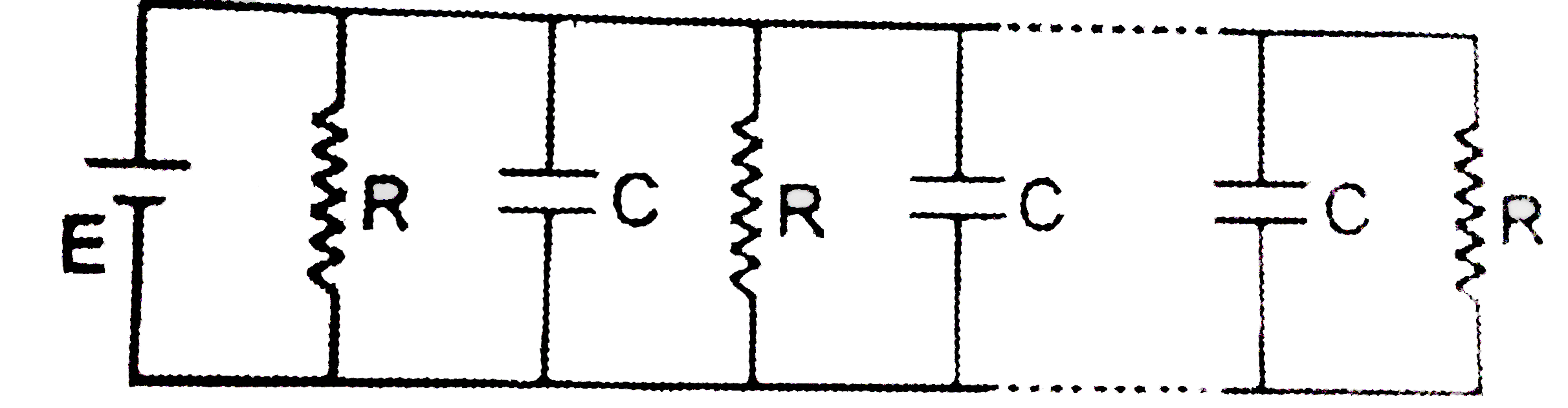
- n resistances each of resistance R are joined with capacitors of ca...
Text Solution
|
- A fresh dry cell of 1.5 volt and two resistors of 10 k Omega each are ...
Text Solution
|
- Refer to the circuit given below. Initially the switch S is in positio...
Text Solution
|
- The capacitance of a parallel plate condenser is C(0) If a dielectric...
Text Solution
|
- A parallel plate capacitor without any dielectric has capacitance C(0)...
Text Solution
|
- An isolated metallic object is charged in vacuum to a potential V(0) u...
Text Solution
|
- Consider a parallel plate capacitor. When half of the space between t...
Text Solution
|
- A network of six identical capacitors, each of capacitance C is for...
Text Solution
|
- Both the capacitors shown in figure are made of square plates of edg...
Text Solution
|
- The particle P shown in the figure has a mass m and a charge -q. Eac...
Text Solution
|
- A capacitor of capacitance 2.0 mu F is charged to a potential differ...
Text Solution
|
- Four capacitors of capacitance 10 mu F and a battery of 2V are arrang...
Text Solution
|
- A part of circuit in a steady state along with the current flowing in ...
Text Solution
|
- Five capacitors are connected as shown in the figure. Initially S is ...
Text Solution
|
- In steady state, find the charge on the capacitor in (mu C) shown in...
Text Solution
|
- Calculate the steady state current (in A ) in the 2 mu resistor shown ...
Text Solution
|
- Find the potential difference between points A and B (in V) of the s...
Text Solution
|
- (i) What is the final potential (in V) of point b with respect to gr...
Text Solution
|