Home
Class 12
PHYSICS
(i) What is the final potential (in V) ...

(i) What is the final potential (in V) of point b with respect to ground in steady state after switch S is closed ?
(ii) How much charge flows through switch S from b to a after it is closed in `mu C`.

Text Solution

Verified by Experts

The correct Answer is:
(i) 6 (ii) 54
Promotional Banner

Topper's Solved these Questions

  • CAPACITANCE

    RESONANCE|Exercise Exercise - 3|26 Videos
  • CAPACITANCE

    RESONANCE|Exercise High Level Problems|16 Videos
  • CAPACITANCE

    RESONANCE|Exercise Exercise - 1|79 Videos
  • ATOMIC PHYSICS

    RESONANCE|Exercise Advanved level problems|17 Videos
  • COMMUNICATION SYSTEMS

    RESONANCE|Exercise Exercise 3|13 Videos

Similar Questions

Explore conceptually related problems

(a) What is the potential of point a with respect to point b in figure, when switch S is open? (b) Which point, a or b , is at the higher potential? (c) What is the final potential of point b with respect to ground when switch S is closed? (d) How much charge flows through switch S when it is closed?

The flow of charge through switch S if it is closed is

Current drawn by the battery just after switch 'S' is closed is :

Current drawn by the battery just after switch 'S' is closed is :-

The connections shown in figure are established with the switch S open. How much charge will flow through the switch if it is closed ? .

(a) What is the steady state potential of point a with respect to point b in figure when switch S is open? (b) Which point, a or b , is at the higher potential? (c) What is the final potential of point b with respect to ground when switch S is closed? (d) How much does the charge on each capacitor change when S is closed?

The connnections shown in figure are established with the swithc S open. How much charge will flow through the switch if it is closed?

Four uncharged capacitors are charged by 24V battery as shown in the figure. How much charge flows through switch S when it is closed?

RESONANCE-CAPACITANCE-Exercise - 2
  1. Calculate the steady state current (in A ) in the 2 mu resistor shown ...

    Text Solution

    |

  2. Find the potential difference between points A and B (in V) of the s...

    Text Solution

    |

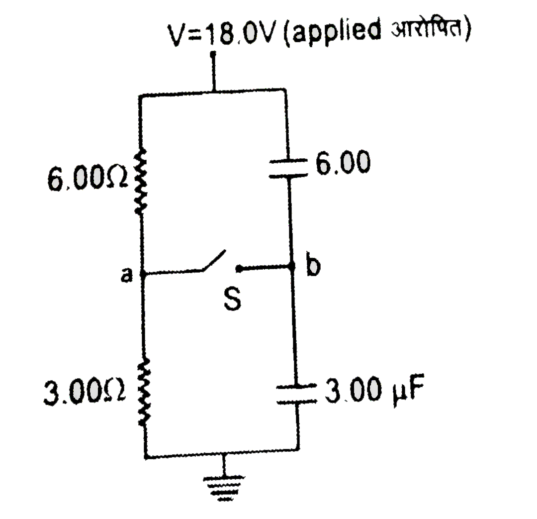
  3. (i) What is the final potential (in V) of point b with respect to gr...

    Text Solution

    |

  4. Find the equivalent capacitance in (mu F) of the infinite ladder show...

    Text Solution

    |

  5. The equivalent capacitance of the combination shown in the figure be...

    Text Solution

    |

  6. The electric field between the plates of a parallel-plate capacitor of...

    Text Solution

    |

  7. A capacitor of capacitance C charged by battery at V volt and then di...

    Text Solution

    |

  8. Hard rubber has a dielectric constant of 2.8 and a dielectric strengh...

    Text Solution

    |

  9. Two square metal plates of side 1 m are kept 0.01 m apart like a paral...

    Text Solution

    |

  10. Three conducting plates of area 500 cm^(2) area kept fixed as shown....

    Text Solution

    |

  11. Consider the arrangement of parallel plates of the previous problem. ...

    Text Solution

    |

  12. For a charged parallel plate capacitor shown in the figure, the force ...

    Text Solution

    |

  13. On a parallel plate capacitor following operations can be performed ...

    Text Solution

    |

  14. In an isolated parallel plate capacitor of capacitance C the four su...

    Text Solution

    |

  15. In the figure shown the plates of a parallel plate capacitor have uneq...

    Text Solution

    |

  16. Rows of capacitors 1,2,4,8 …..infty capacitors, each of capacitance 2 ...

    Text Solution

    |

  17. Shows a diagonal symmetric arrangement of capacitors and a battery. ...

    Text Solution

    |

  18. Two capacitors of 2muF and 3muF are charged to 150 V and 120 V, respec...

    Text Solution

    |

  19. In the adjoining diagram all the capacitors are initially uncharged, ...

    Text Solution

    |

  20. In the circuit shown in figure the switch S is closed at t = 0. A lo...

    Text Solution

    |