Home
Class 12
PHYSICS
Two capacitors of 2muF and 3muF are char...

Two capacitors of `2muF` and `3muF` are charged to `150 V` and `120 V`, respectively. The plates of capacitor are connected as shown in the figure. An uncharged capacitor of capacity `1.5muF` falls to the free end of the wire. Then

A

Charge on the `1.5 mu F` capacitor will become `180 mu C` at steady state.

B

Charge on the `2mu F` capacitor will become `120 mu C` at steady state.

C

Positive charge flows through point A from left to right.

D

Positive charge flows through point A from right to left .

Text Solution

Verified by Experts

The correct Answer is:
A, B, C
Promotional Banner

Topper's Solved these Questions

  • CAPACITANCE

    RESONANCE|Exercise Exercise - 3|26 Videos
  • CAPACITANCE

    RESONANCE|Exercise High Level Problems|16 Videos
  • CAPACITANCE

    RESONANCE|Exercise Exercise - 1|79 Videos
  • ATOMIC PHYSICS

    RESONANCE|Exercise Advanved level problems|17 Videos
  • COMMUNICATION SYSTEMS

    RESONANCE|Exercise Exercise 3|13 Videos

Similar Questions

Explore conceptually related problems

In the circuit shown in figure charge stored in the capacitor of capacity 5muF is

Two capacitors A and B with capacities 3muF and 2muF are charged to a potential difference of 100 V and 180V , respectively. The plates of the capacitors are connected as show in figure with one wire of each capacitor free. The upper plate of A is positive and that of B is negastive. An uncharged 2muF capcitor C with lead wires falls on the free ends to complete the circuit. Calculate a. the final charge on the three capacitors. b. the amount of electrostatic energy stored in the system before and after completion of the circuit.

Two cellls, two resistance and two capacitors are connected as shown in figure. The charge on 2muF capacitors is

Two capacitors A and B with capacities 3 muF and 2 muF are charged to a potential differece of 100 V and 180 V , respectively. The plates ot the capacitors are connected as shown in, with one wire free from each capacitor. The upper plate of A is positive and that of B is negative An uncharged 2muF capacitor C with lead wires falls on the free ends to complete the circuit. i. Calculate the final charge on the three capacitors, ii. Find the amount of electrostatic energy stored in the system before and after the completion of the circuit. .

Two capacitors A and B with capacitors 3 muF and 2 muF are charged to a potential difference of 100 V and 180 V respectively. One plate of two capacitors are connected as shown. Now switch S is closed so as to connect a cell of 100 V to the free plates of two capacitors. (a) Find charge on the two capacitors after the switch is closed. (b) Calculate heat generated in the circuit

For the circuit shown in figure the charge on 4muF capacitor is

Two capacitors of capacitance 10 muF and 20 muF are charged to potential 20 V and 10 V respectively. If they are connected to share charges, then loss of energy is

For the arrangement shown in the figure, the charge on the 4muF capacitor is

Two capacitors of capacitances 3 muF and 6 muF , are charged to potentials 2V and 5V respectively. These two charged capacitors are connected in series. Find the potential across each of the two capacitors now.

Three capcaitors of capacities 1muF, 2muF and 3muF are charged by 10V, 20V and 30V respectively. Now positive plates of first two capacitors are connected with the negative plate of third capacitor on one side and negative plates of first wo capacitors are connectes with positive of third capacitor on the other side. Find a. common potential V b. final charges on different capacitors.

RESONANCE-CAPACITANCE-Exercise - 2
  1. Rows of capacitors 1,2,4,8 …..infty capacitors, each of capacitance 2 ...

    Text Solution

    |

  2. Shows a diagonal symmetric arrangement of capacitors and a battery. ...

    Text Solution

    |

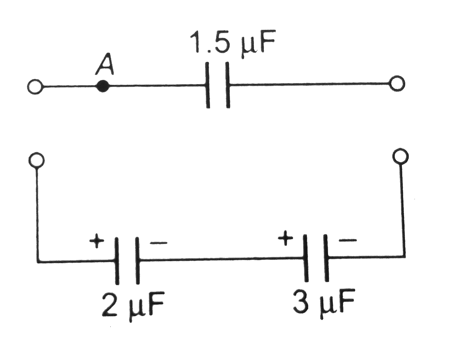
  3. Two capacitors of 2muF and 3muF are charged to 150 V and 120 V, respec...

    Text Solution

    |

  4. In the adjoining diagram all the capacitors are initially uncharged, ...

    Text Solution

    |

  5. In the circuit shown in figure the switch S is closed at t = 0. A lo...

    Text Solution

    |

  6. When a charged capacitor is connected with an uncharged capacitor , t...

    Text Solution

    |

  7. In the circuit shown each capacitor has a capcitance C. The emf of the...

    Text Solution

    |

  8. Two similar condensers are connected in parallel and are charged to...

    Text Solution

    |

  9. We have a combination as shown in following figure. Choose the corre...

    Text Solution

    |

  10. The charge across the capacitor in two different RC circuit 1 and 2 ar...

    Text Solution

    |

  11. The instantaneous charge on capacitor in two discharging RC circuils...

    Text Solution

    |

  12. Capacitor C1 of capacitance 1 micro-farad and capacitor C2 of capacita...

    Text Solution

    |

  13. The terminals of a battery of emf V are connected to the two plates of...

    Text Solution

    |

  14. A parallel plate capacitor of plate area A and plate separation d is c...

    Text Solution

    |

  15. The plates of a parallel plate capacitor with no dielectirc are connec...

    Text Solution

    |

  16. A parallel plate capacitor has a dielectric slab in it. The slab jus...

    Text Solution

    |

  17. A parallel plate air capacitor is connected to a battery. The quantiti...

    Text Solution

    |

  18. Capacitor C(3) in the circuit is a veriable capacitor (its capacitance...

    Text Solution

    |

  19. Capacitor C(3) in the circuit is a veriable capacitor (its capacitance...

    Text Solution

    |

  20. Capacitor C(3) in the circuit is a veriable capacitor (its capacitance...

    Text Solution

    |