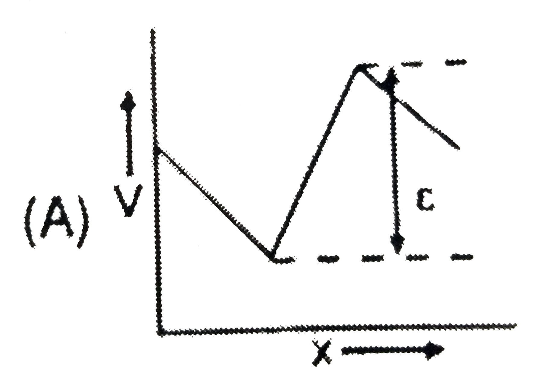
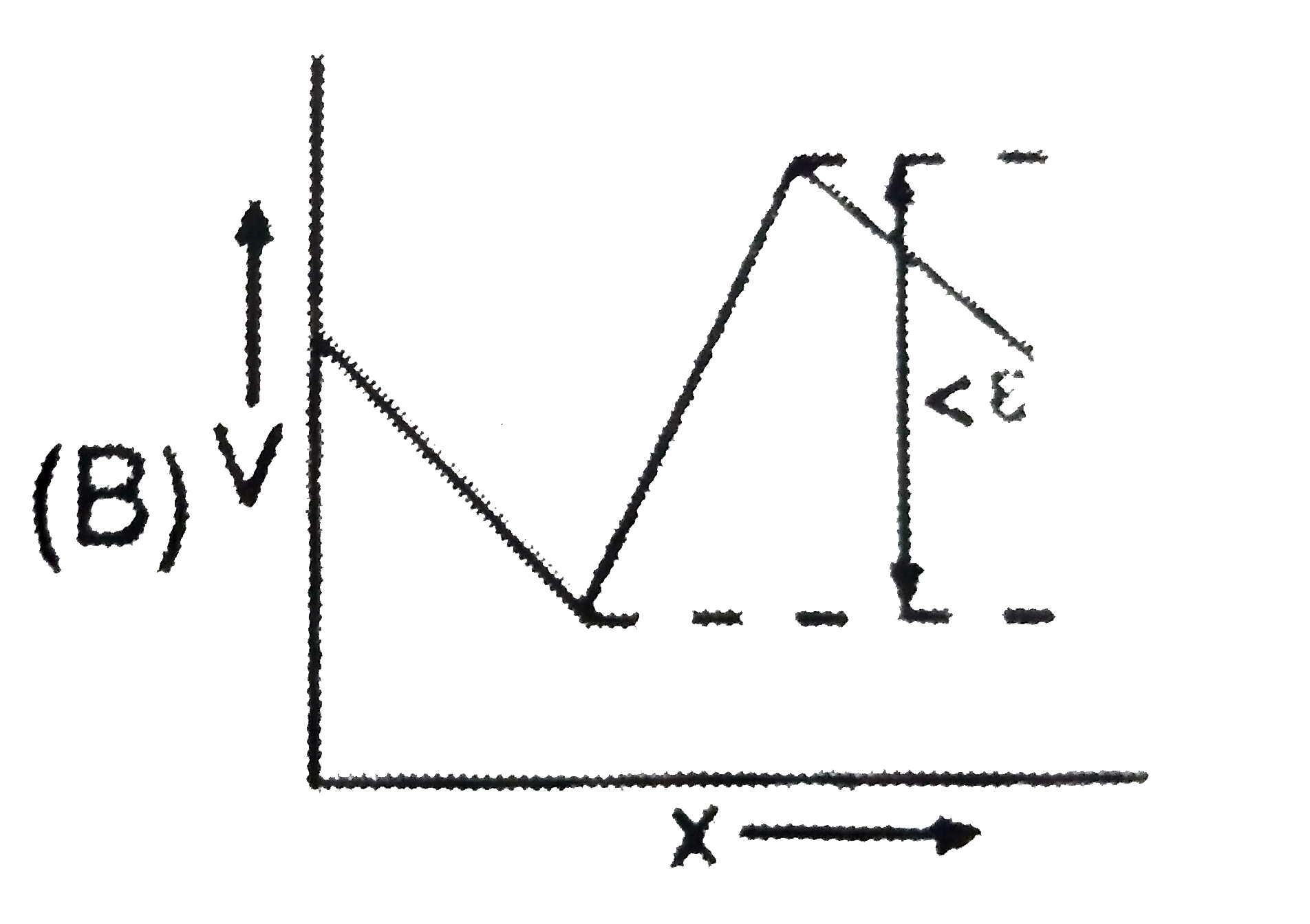
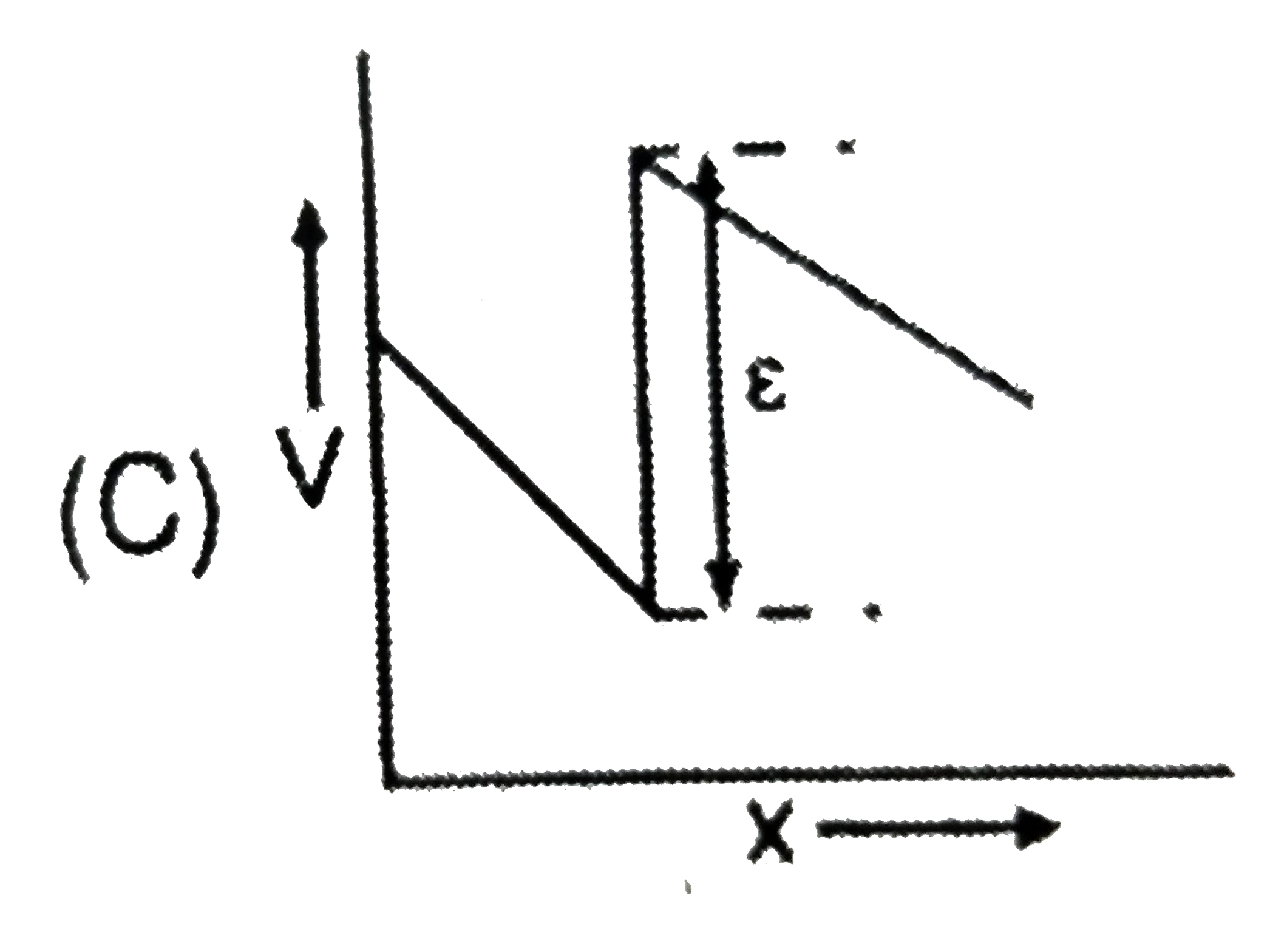
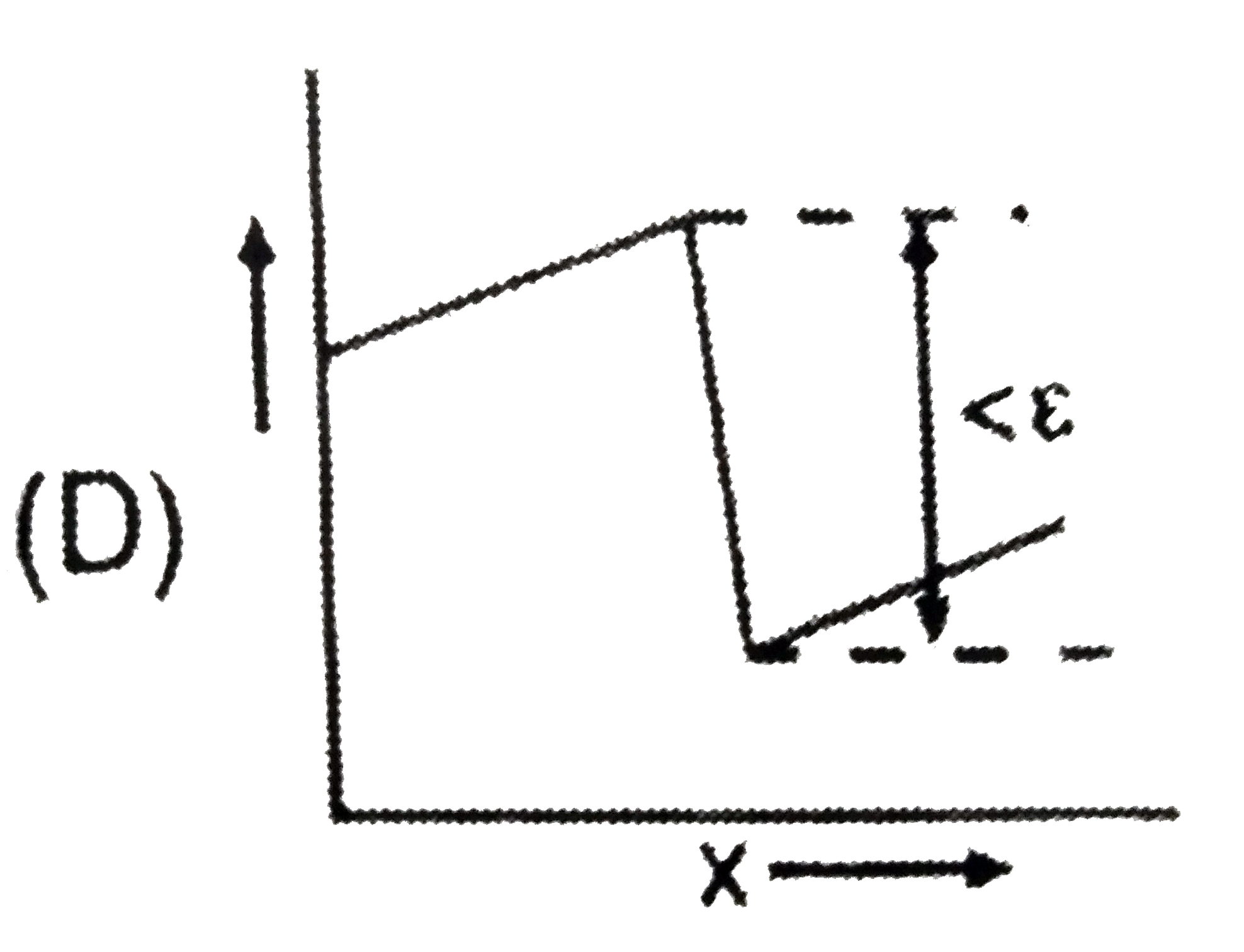
Home
Class 12
PHYSICS
The two ends of a uniform conductor are ...

The two ends of a uniform conductor are joined to a cell of e.m.f. `E` and some internal resistance. Starting from the midpoint `P` of the conductor, we move in the direction of current and return to `P`. The potential `V` at every point on the path is plotted against the distance covered `(x)`. which of the following graphs best represent the resulting curve ?

A

B

C

D

Text Solution

Verified by Experts

The correct Answer is:
B
Promotional Banner

Topper's Solved these Questions

  • CURRENT ELECTRICITY

    RESONANCE|Exercise Exercise-2 (Part-2)|16 Videos
  • CURRENT ELECTRICITY

    RESONANCE|Exercise Exercise-2 (Part-3)|22 Videos
  • CURRENT ELECTRICITY

    RESONANCE|Exercise Exercise-1 (Part-3)|2 Videos
  • COMMUNICATION SYSTEMS

    RESONANCE|Exercise Exercise 3|13 Videos
  • DAILY PRACTICE PROBLEM

    RESONANCE|Exercise DPP.No.71|1 Videos

Similar Questions

Explore conceptually related problems

A thin, straight conductor lies along the axis of a hollow conductor of radius R . The two carry equal currents in the same direction. The magnetic field B is plotted against the distance r from the axis. Which of the following best represents the resulting curve?

A square, conducting loop falls from rest in the xy-plane. There is a uniform magnetic field in the z-direction below the x-axis. The velocity v of the loop is plotted against time t. Which of the following best represents the resulting curve

A current of two amperes is flowing through a cell of e.m.f. 5 volts and internal resistance 0.5 ohm from negative to positive electrode. If the potential of negative electrode is 10 V , the potential of positive electrode will be

Two ideantical point charges are placed at a separation of d . P is a point on the line joining the charges, at a distance x from any one charge. The field at P is E, E is plotted against x for value of x from close to zero to slightly less then d . Which of the following represents the resulting curve

E denotes electric field in a uniform conductor, I corresponding current through it, v_(d) velocity of electrons and P denotes thermal power produced in the conductor, then which of the following graph is correct?

A battery of e.m.f. 2 V and internal resistance 2Omega is connected to an external resistance 8Omega . If the length of the conductor is 4 m, then potential gradient between the two ends of the wire is

Two batteries of e.m.f. 4V and 8V with internal resistances 1 Omega and 2 Omega are connected in a circuit with a resistance of 9 Omega as shown in figure. The current and potential difference between the points P and Q

RESONANCE-CURRENT ELECTRICITY-Exercise-2 (Part-1)
  1. If a copper wire is stretched to make its radius decrease by 0.1%, the...

    Text Solution

    |

  2. The potential difference between the terminals of a battery of emf 6.0...

    Text Solution

    |

  3. The two ends of a uniform conductor are joined to a cell of e.m.f. E a...

    Text Solution

    |

  4. A cell of emf E having an internal resistance R varies with R as shown...

    Text Solution

    |

  5. In a circuit shown in Fig, resistances R(1) and R(2) are known , as w...

    Text Solution

    |

  6. A resistor R is conneted to a parallel combination of two identical ba...

    Text Solution

    |

  7. The equivalent resistance between A and B will be (in Omega)

    Text Solution

    |

  8. Six wires each of resistance r form a tetrahedron. The equivalent resi...

    Text Solution

    |

  9. The equivalent resistance between points A and B is

    Text Solution

    |

  10. In the question find the resistacnce between points 1-3.

    Text Solution

    |

  11. The effective resistance between points P and Q of the electrical ci...

    Text Solution

    |

  12. A 100 W bulb B(1) and two 60 W bulbs B(2) and B(3), are connected to a...

    Text Solution

    |

  13. When a galvanometer is shunted with a 4 Omega resistance, the deflecti...

    Text Solution

    |

  14. In the circuit shown the reading of ammeter and voltmeter are 4 A and ...

    Text Solution

    |

  15. In the circuit shown in figure, reading of voltmeter is V1 when only S...

    Text Solution

    |

  16. If the reading of ammeter A(3) in figure is 0.75 A. Neglecting the res...

    Text Solution

    |

  17. In the previous question the reading of ammeter A(1) will be :

    Text Solution

    |

  18. The resistance of the shown in figure is 30 Omega. Neglecting the amme...

    Text Solution

    |

  19. An ammeter and a voltmeter are joined in sereis to a cell. Their readi...

    Text Solution

    |

  20. An ammeter and a voltmeter are connected in series to a battery of emf...

    Text Solution

    |