Text Solution
Verified by Experts
The correct Answer is:


Topper's Solved these Questions
CURRENT ELECTRICITY
RESONANCE|Exercise Exercise-2 (Part-3)|22 VideosCURRENT ELECTRICITY
RESONANCE|Exercise Exercise-2 (Part-4)|12 VideosCURRENT ELECTRICITY
RESONANCE|Exercise Exercise-2 (Part-1)|25 VideosCOMMUNICATION SYSTEMS
RESONANCE|Exercise Exercise 3|13 VideosDAILY PRACTICE PROBLEM
RESONANCE|Exercise DPP.No.71|1 Videos
Similar Questions
Explore conceptually related problems
RESONANCE-CURRENT ELECTRICITY-Exercise-2 (Part-2)
- The current density in a cylindrical conductor of radius R varies acco...
Text Solution
|
- 1 meter long metallic wire is broken into two unequal parts P and Q. ...
Text Solution
|
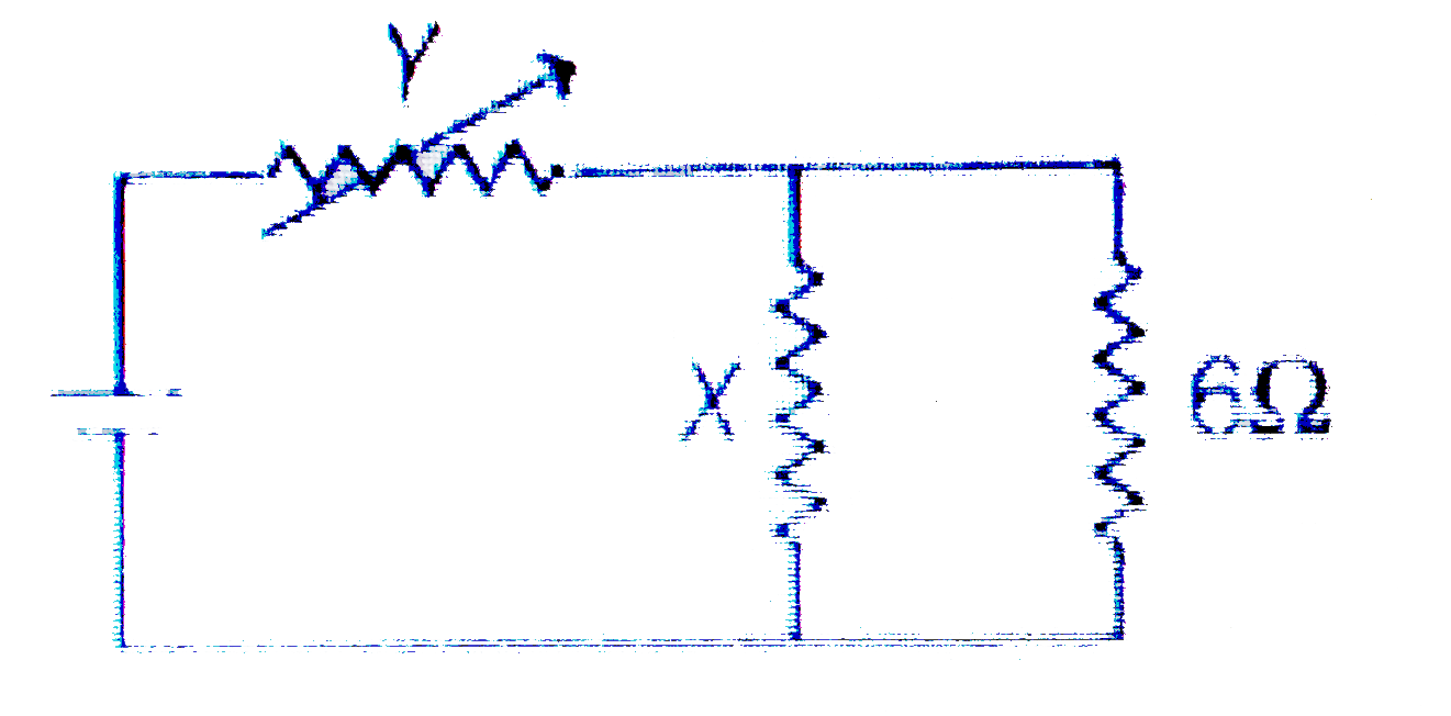
- In the figur shown, the thermal power generated in 'Y' is maximum when...
Text Solution
|
- A series parallel combination battery consisting of a large number N ...
Text Solution
|
- The internal resistance of an accumulator battery of emf 6V is 10(Omeg...
Text Solution
|
- A hemispherical network of radius a is made by using a conducting wire...
Text Solution
|
- Find the resistance in ohm of a wire frame shaped as a cube (figure) w...
Text Solution
|
- The figure is made of a uniform wire and represnts a regular five poin...
Text Solution
|
- In the circuit shown in fig. E(1)=3" volt",E(2)=2" volt",E(3)=1" vole ...
Text Solution
|
- The resistance of each resisor in the circuit diagram shown in figure ...
Text Solution
|
- In the circuit shown in figure 16, E, F, G and H are cells of emf 2...
Text Solution
|
- If the galvanometer in the circuit of figure reads zero, calculate the...
Text Solution
|
- Shown an arrangement to measure the emf (epsilon)and internal resistan...
Text Solution
|
- In the circuit shown, reading of the voltmeter connected across 400 Om...
Text Solution
|
- In the given circuit the ammeter A(1)" and "A(2) are ideal and the amm...
Text Solution
|
- Two resistors, 400 Omega, " and "800 Omega are connected in series wit...
Text Solution
|