Text Solution
Verified by Experts


Topper's Solved these Questions
SEMICONDUCTOR ELECTRONICS METERIALS DEVICES AND SIMPLE CIRCUITS
MODERN PUBLICATION|Exercise CONCEPUAL QUESTIONS|37 VideosSEMICONDUCTOR ELECTRONICS METERIALS DEVICES AND SIMPLE CIRCUITS
MODERN PUBLICATION|Exercise TOUGH & TRICKY PROBLEMS|10 VideosSEMICONDUCTOR ELECTRONICS METERIALS DEVICES AND SIMPLE CIRCUITS
MODERN PUBLICATION|Exercise CHAPTER PRACTICE TEST FOR BOARD EXAMINATION|12 VideosRAY OPTICS AND OPTICAL INSTRUMENTS
MODERN PUBLICATION|Exercise CHAPTER PRACTICE TEST|14 VideosWAVE OPTICAL
MODERN PUBLICATION|Exercise CHAPTER PRACTICE TEST|7 Videos
Similar Questions
Explore conceptually related problems
MODERN PUBLICATION-SEMICONDUCTOR ELECTRONICS METERIALS DEVICES AND SIMPLE CIRCUITS -PRACTICE PROBLEMS
- The fobbidden gap in an ntype semiconductor is 4 me v so that the ele...
Text Solution
|
- A type semiconductor sample has electron and hole concentration of 1...
Text Solution
|
- The value of forward current in ap-n junction at 0.1 V is 1.04 xx10^(-...
Text Solution
|
- The values of v and I for silicon diode is given as follows Using...
Text Solution
|
- Voltage drop across a p-n junction in forward bias is 0.5 V a battery ...
Text Solution
|
- A p-n junction diode in forward bias is connected to a battery of 4 V...
Text Solution
|
- Two diodes with internal resistance of 20 omega each are used in a ful...
Text Solution
|
- The rms value of input voltage in a full wave rectifier is 12 V determ...
Text Solution
|
- In a Zener regulated power supply a Zener diode with V(Z) = 6.0 V is u...
Text Solution
|
- A 10V of zener diode is connected in series to a resistance across a ...
Text Solution
|
- From the output characteristics of common emitter circuit shown in Fig...
Text Solution
|
- In a common emitter transistor the potential drop across the collect...
Text Solution
|
- In a common base transistor the value of load resistance in output a...
Text Solution
|
- In a semiconductor transistor there is change in collector current of ...
Text Solution
|
- In common emitter transistor as shown in Fig., the V(BB) supply can be...
Text Solution
|
- For a CE transistor amplifier the audio signal voltage across the col...
Text Solution
|
- Which gate is represented by the given truth table
Text Solution
|
- You are given a circuit below write its truth table hence identify t...
Text Solution
|
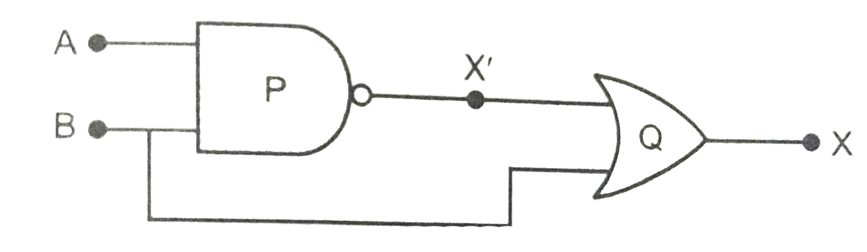
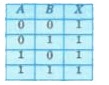
- Identify the logic gates marked P and Q in the circuit Fig. Write the ...
Text Solution
|
- Write the truth table for the given combination of gates
Text Solution
|