Home
Class 12
PHYSICS
If the resistance R(1) is increased ho...

If the resistance `R_(1)` is increased how will the reading of the ammeter and voltmeter change

Text Solution

Verified by Experts

Redrawing the circuit diagram with marking of current and voltage

From the circuit diagram
`i_(g) R_(1) = V_(BB) - V_(ee)`
if `R_(1) ` is increased `i_(B)` will decrease
`So ` if `i_(B)` decreased `I_(C)` is also decreased So there is a decrease in ammeter and voltmeter readings.
Promotional Banner

Topper's Solved these Questions

  • SEMICONDUCTOR ELECTRONICS METERIALS DEVICES AND SIMPLE CIRCUITS

    MODERN PUBLICATION|Exercise HIGER ORDER THINKING SKILLS & ADVANCED LEVEL|11 Videos
  • SEMICONDUCTOR ELECTRONICS METERIALS DEVICES AND SIMPLE CIRCUITS

    MODERN PUBLICATION|Exercise REVISION EXERCISES (VERY SHORT ANSWER QUESTION)|61 Videos
  • SEMICONDUCTOR ELECTRONICS METERIALS DEVICES AND SIMPLE CIRCUITS

    MODERN PUBLICATION|Exercise TOUGH & TRICKY PROBLEMS|10 Videos
  • RAY OPTICS AND OPTICAL INSTRUMENTS

    MODERN PUBLICATION|Exercise CHAPTER PRACTICE TEST|14 Videos
  • WAVE OPTICAL

    MODERN PUBLICATION|Exercise CHAPTER PRACTICE TEST|7 Videos

Similar Questions

Explore conceptually related problems

If the resistance R_(1) is increased (see figure), how will the reading of the ammeter and voltmeter change ?

In the circuit shown, the reading of the voltmeter and the ammeter are

If by mistake Ammeter is connected parallel to the resistance then i-V curve expected is (Here i = reading of ammeter, V= reading of voltmeter)

An ammeter and a voltmeter are initially connected in series to a battery of zero internal resistance. When switch S_(1) is closed the reading of the voltmeter becomes half of the initial, whereas the reading of the ammeter becomes double. If now switch S_(2) is also closed, then reading of ammeter becomes :

An ideal ammeter (zero resistance) and an idel voltmeter (infinite resistance) are connect as shows in Fig. 6.47 . The ammeter and the voltmeter readings are

In the given circuit the readings of the voltmeter V_(1) and the ammeter A are .

A galvanometer (coil resistance 99 Omega .) is converted into an ammeter using a shunt of 1 Omega and connected as shown in figure (a). The ammeter reads 3 A . The same galvanometer is convened into a voltmeter by connecting a resistance of 101 Omega in series. This voltmeter is connected at, shown in figure (b). Its reading is found to be 4/5 of the full scale reading. Find : (a) internal resistance r of the cell (b) range of the ammeter and voltmeter (c) full scale deflection current of the galvanometer.

The ammeter A reads 2A and the voltmeter V reads 20V, the value of resistance R is (Assuming finite resistance's of ammeter and voltmeter)

An ammeter of zero resistance and a volt meter are connected in series to a battery of emf 6.0 volt and certain internal resistance. When a resistance R is connected in parallel with the voltmeter the readings of the voltmeter becomes half of its initial reading and the reading of the ammeter becomes 2 times to its initial reading (before R is connected). Find the voltmeter reading in volt after the connection of the resistance.

MODERN PUBLICATION-SEMICONDUCTOR ELECTRONICS METERIALS DEVICES AND SIMPLE CIRCUITS -NCERT FILE SOLVED (TEXT BOOK EXERCISES )
  1. A p-n photodiode is fabricated from a semiconductor with band gap of...

    Text Solution

    |

  2. The number of silicon atoms per m^(3) is 5xx10^(28). This is doped sim...

    Text Solution

    |

  3. In an intrinsic semiconductor, the energy gap E(g) of an intrinsic sem...

    Text Solution

    |

  4. In a p-n junction diode, the currect I can expressed as I=I(0) exp((eV...

    Text Solution

    |

  5. You are given two circuits as given below show that circuit (a) acts ...

    Text Solution

    |

  6. Write the truth table for a NAND gae connected as given in the follow...

    Text Solution

    |

  7. Why are elemental dopants for Silicon or Germanium usually chosen fro...

    Text Solution

    |

  8. Sn, C, Si and Ge are all group XIV elements . Yet , Sn is a conductor ...

    Text Solution

    |

  9. Can the potential barrier across a p-n junction be measured by simply ...

    Text Solution

    |

  10. Draw the output wave form across the resistor

    Text Solution

    |

  11. The amplifiers X, Y and Z are connected in series. If the voltage gain...

    Text Solution

    |

  12. In a CE transistor amplifier, there is a current and voltage gain asso...

    Text Solution

    |

  13. (i) Name the type of a diode whose characteristics are shown in figure...

    Text Solution

    |

  14. Three photodiodes D1 , D2 and D3 are made of semiconductors having ...

    Text Solution

    |

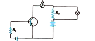
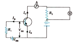
  15. If the resistance R(1) is increased how will the reading of the amme...

    Text Solution

    |

  16. Two car garages have a common gate which needs to open automatically w...

    Text Solution

    |

  17. How would you set up a circuit to obtain NOT gate using a transistor?

    Text Solution

    |

  18. Explain why elemental semiconductor cannot be used to make visible LED...

    Text Solution

    |

  19. Write the truth table for the circuit shown in name the gate that the...

    Text Solution

    |

  20. A Zener of power rating 1 W is to be used as a voltage regulator. If Z...

    Text Solution

    |