Home
Class 12
PHYSICS
In the circuit shown , R1=4Omega, R2=R3 ...

In the circuit shown , `R_1=4Omega, R_2=R_3 =15Omega, R_4 = 30 Omega ` and `epsi = 10V` . Calculate the equivalent resistance of the circuit and the current in each resistor.

Text Solution

Verified by Experts


The given circuit can be redrawn as shown in Fig. Here `R_2 , R_3` and `R_4` are in parallel and their combined resistance R. will be
`(1)/(R.) = (1)/(R_2) + (1)/(R_3) + (1)/(R_4) = 1/15 + 1/15 + 1/30 = (2 + 2 + 1)/(30) = 5/30`
` rArr R. = 6Omega`
Now R. and `R_1` are in series, hence equivalent resistance of the circuit
`R = R. + R_1 = 6Omega +4Omega = 10 Omega`
Main circuit current `I_1 = E/R = (10V)/(10 Omega) = 1 A `
`I_2 + I_3 + I_4 = I_1 = 1A`
and potential difference between A and B remains constant, i.e.,
`15I_2 = 15I_3 = 30 I_4`
` rArr I_2 = I_3 = 2I_4`
Therefore, on simplifying, we get
`I_2 = I_3 = 0.4A` and `I_4 = 0.2 A `
Promotional Banner

Topper's Solved these Questions

  • CURRENT ELECTRICITY

    U-LIKE SERIES|Exercise LONG ANSWER QUESTIONS - II|8 Videos
  • CURRENT ELECTRICITY

    U-LIKE SERIES|Exercise SELF ASSESSMENT TEST (SECTION A (MULTIPLE CHOICE QUESTIONS))|6 Videos
  • CURRENT ELECTRICITY

    U-LIKE SERIES|Exercise SHORT ANSWER QUESTIONS|42 Videos
  • CBSE SAMPLE QUESTION PAPER 2019-20 (SOLVED)

    U-LIKE SERIES|Exercise SECTION D|6 Videos
  • DUAL NATURE OF RADIATION AND MATTER

    U-LIKE SERIES|Exercise SELF ASSESSMENT TEST SECTION-C (VERY SHORT ANSWER QUESTIONS)|3 Videos

Similar Questions

Explore conceptually related problems

In the circuit shown, R_1=4Omega,R_2=R_3=15Omega,R_4=30OmegaandE=10V . Caculate the equivalent resistance of te circuit and the current in each resistor.

In the circuit R_(1) = 4 Omega , R_(2) = R_(3) = 15 Omega R_(4) = 30 Omega and E = 10 V Calculate the equivalent resistance of the circuit and current in each resistor

In the circuit shown in Fig. 4.19. R_(1)=100 Omega, R_(2)=R_(3)=50 Omega, R_(4)=75 Omega and E=4.75 V. Work out the equivalent resistance of the circuit and the current in each resistor.

In the circuit shown, R_1=2 Omega,R_2=R_3=10Omega and E=6V . Work out the equivalent resistance of the circuit and the current in each resistor.

In the circuit given E = 6.0 volt, R_(1) = 100Omega, R_(2) = R_(3)=50Omega and R_(4)=75Omega . The equivalent resistance of the circuit, in ohms is

In the circuit shown in fig. R_(1) = 10 Omega, R_(2) = Omega, C_(1) = 1 muF, C_(2) = 2muF, and E =6V. Calculate the charge on each capactor in the stedy state.

For the circuit shown in the figure, the current in the 4 Omega resistor is

(a) Resistors given as R_(1), R_(2) and R_(3) are connected in series to a battery V. Draw the circuit diagram showing the arrangement. Derive an expression for the equivalent resistance of the combination. (b) If R_(1)=10 Omega, R_(2)=20 Omega and R_(3)=30 Omega , calculate the effective resistance when they are connected in series to a battery of 6 V. Also find the current flowing in the circuit.

In the circuit shown in adjoining fig E =10V, R_(1)=1 Omega R_(2)=2 Omega, R_(3)=3 Omega and L=2H . Calculate the value of current i_(1), i_(2) and i_(3) immidiately after key S is closed :-

U-LIKE SERIES-CURRENT ELECTRICITY -LONG ANSWER QUESTIONS - I
  1. The reading of an ideal ammeter, in the circuit shown here, equals (i)...

    Text Solution

    |

  2. For the potentiometer circuit shown in the given figure, points X and ...

    Text Solution

    |

  3. (a) For the circuit shown in the figure, how would the balancing lengt...

    Text Solution

    |

  4. Two cells of emf 1.5 V and 2 V and internal resistance 1Omega and 2Ome...

    Text Solution

    |

  5. Calculate the value of the resistance R in the circuit shown in Fig. s...

    Text Solution

    |

  6. Using Kirchhoff's rules determine the value of unknown resistance R in...

    Text Solution

    |

  7. State Kirchhoff's rules of current distribution in an electrical netwo...

    Text Solution

    |

  8. State Kirchhoff's rules. Use these rules to write the expressions for ...

    Text Solution

    |

  9. State Kirchhoff's rules. Apply these rules to the loops PRSP and PRQP...

    Text Solution

    |

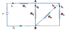
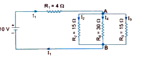
  10. In the circuit shown , R1=4Omega, R2=R3 =15Omega, R4 = 30 Omega and e...

    Text Solution

    |

  11. Two cells of same emf epsi but internal resistances r1 and r2 are co...

    Text Solution

    |

  12. In the electric network shown in the Fig., use Kirchhoff's rules to ca...

    Text Solution

    |

  13. Using Kirchhoff's rules, calculate the potential difference between B ...

    Text Solution

    |

  14. Two heating elements of resistances R1 and R2 when operated at a cons...

    Text Solution

    |

  15. A potentiometer wire of length 1 m is connected to a driver cell of e...

    Text Solution

    |

  16. A 10 m long wire of uniform cross-section and 20Omega resistance is u...

    Text Solution

    |

  17. A circuit using a potentiometer and battery of negligible internal res...

    Text Solution

    |

  18. In the Fig., a long uniform potentiometer wire AB is having a constan...

    Text Solution

    |

  19. Two conductors are made of the same material and have the same length....

    Text Solution

    |

  20. A potentiometer wire of length 1 m has a resistance of 10 Omega . It i...

    Text Solution

    |