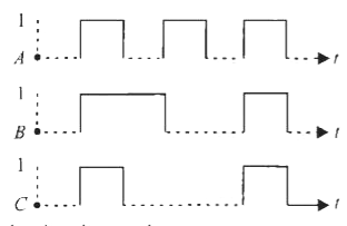
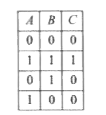
A
B
C
D
Text Solution
Verified by Experts
The correct Answer is:


Topper's Solved these Questions
SOLID STATE ELECTRONS
MTG-WBJEE|Exercise WB JEE WORKOUT (CATEGORY 3 : Single Option Correct Type)|15 VideosSOLID STATE ELECTRONS
MTG-WBJEE|Exercise WB JEE WORKOUT (CATEGORY 3 : One or More than one option Correct Type)|10 VideosPARTICLE NATURE OF LIGHT AND WAVE PARTICLE DUALISM
MTG-WBJEE|Exercise WB JEE PREVIOUS YEARS QUESTIONS|15 VideosTHERMODYNAMICS
MTG-WBJEE|Exercise WB JEE Previous Years Questions|12 Videos
Similar Questions
Explore conceptually related problems
MTG-WBJEE-SOLID STATE ELECTRONS -WB JEE Previous Years Questions (CATEGORY 1 : Single Option Correct Type)
- The following shows a logic gate circuit with two inputs A and B and t...
Text Solution
|
- A NOR gate and a NAND gate are connected shown. Two different sets of ...
Text Solution
|
- In an n-p-n transistor
Text Solution
|
- In a transistor output characteristics commonly used in common emitter...
Text Solution
|
- In the circuit shown below, assume the diode to be ideal. When V(i) in...
Text Solution
|
- The output Y of the logic circuit given below is
Text Solution
|
- If the bandgap between valence band and conduction band in a material ...
Text Solution
|
- Assume that each diode shown has a forward bias resistance of 50Omega ...
Text Solution
|
- The inputs to the digital circuit are shown below. The output Y is
Text Solution
|
- A zener diode having breakdown voltage 5.6 V is connected in reverse b...
Text Solution
|
- In case of a bipolar transistor beta=45. The potential drop across the...
Text Solution
|
- In the given circuit, the binary inputs at A and B are both 1 in one c...
Text Solution
|
- A semiconducting device is connected in a series circuit with a batter...
Text Solution
|
- In the circuit shown, inputs A and B are in states '1' and '0' respect...
Text Solution
|
- What will be the current flowing through the 6kOmega resistor in the c...
Text Solution
|
- Each of the two inputs A and B can assume values either 0 or 1. Then w...
Text Solution
|