Text Solution
Verified by Experts


Topper's Solved these Questions
XII BOARDS
XII BOARDS PREVIOUS YEAR|Exercise C.B.S.E.CLASS-XII PHYSICS (THEORY) [SET-I] (SECTION-A)|5 VideosXII BOARDS
XII BOARDS PREVIOUS YEAR|Exercise SECTIONS-B|6 VideosXII BOARDS
XII BOARDS PREVIOUS YEAR|Exercise SECTION-C|55 VideosSAMPLE PAPER 2019
XII BOARDS PREVIOUS YEAR|Exercise SECTION D|6 Videos
Similar Questions
Explore conceptually related problems
XII BOARDS PREVIOUS YEAR-XII BOARDS-PHYSICS (Theory) DELHI BOARD -2016 [SET -I][COMPTT.]
- A student connects a cell of emf epsilon(2) and internal resistance r(...
Text Solution
|
- Write the expression for the magnetic force vecF acting on a charged p...
Text Solution
|
- A long straight wire of a circular cross-section of radius 'a' carries...
Text Solution
|
- Derive the expression for the torque tau acting on a rectangular curr...
Text Solution
|
- Define self-inductance of a coil and hence write the definition of 'He...
Text Solution
|
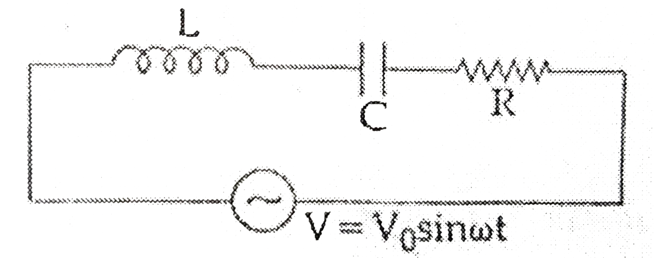
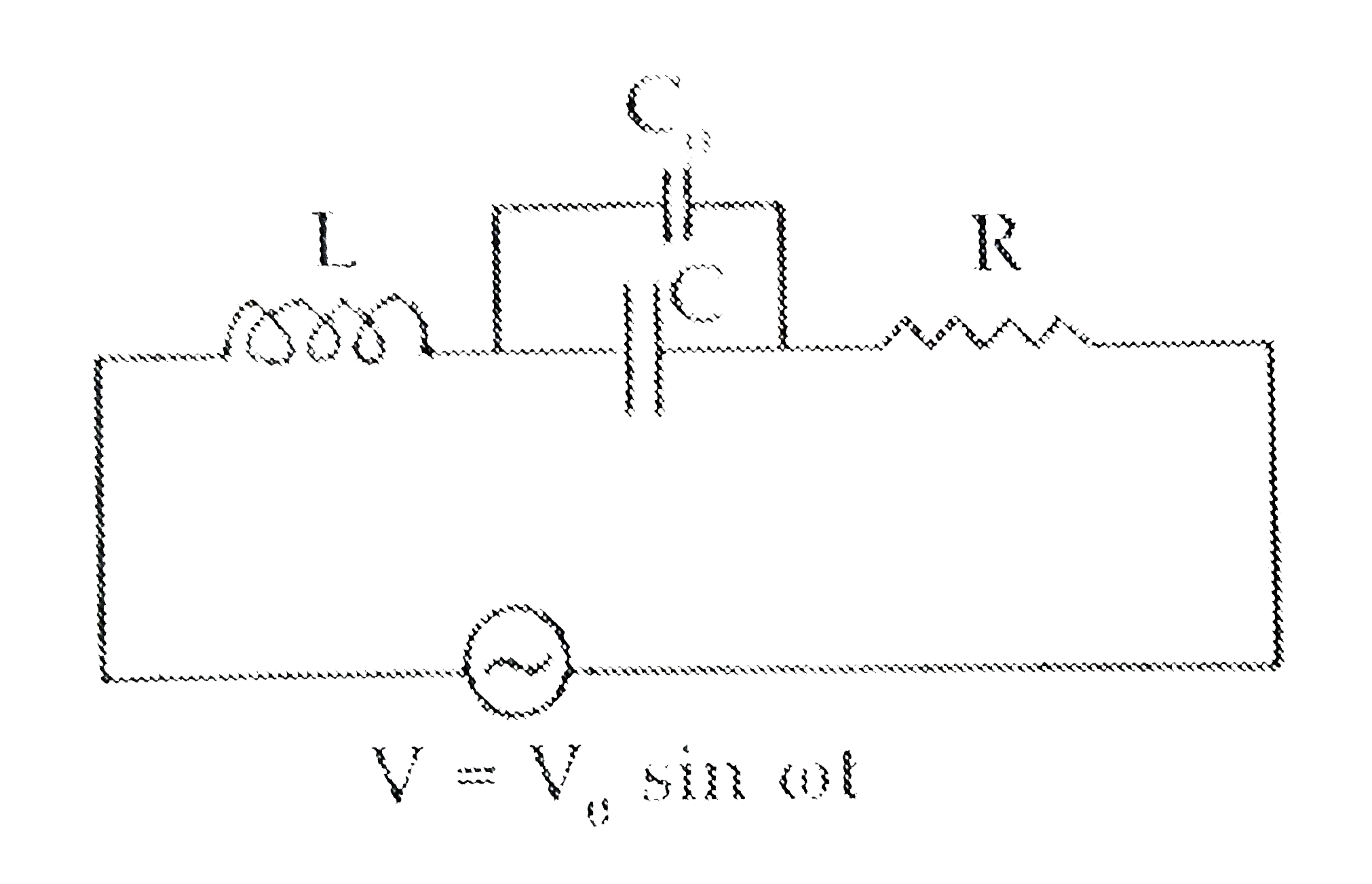
- The current in the LCR circuit shown in the figure is observed to lead...
Text Solution
|
- Point out two distinct features observed experimentally in photolelect...
Text Solution
|
- It is required to design a (two -input) logic gate, using an appropria...
Text Solution
|
- Give (brief) reasons for the following : (a) We use 'sky wave' mode ...
Text Solution
|
- A parallel plate capacitar, of capacitance, 20 mu F, is connected to a...
Text Solution
|
- A convex lens, of focal length 25 cm, and a concave mirror, of radius ...
Text Solution
|
- A 200 Mh (pure) inductor, and a 5muF (pure) capacitor , are connected ...
Text Solution
|