Text Solution
Verified by Experts


Topper's Solved these Questions
Similar Questions
Explore conceptually related problems
XII BOARDS PREVIOUS YEAR-XII BOARDS-SECTION - C
- Four point charges Q, q, Q and q are placed at the corners of a square...
Text Solution
|
- (a) Three point charges q,-4q and 2q are placed at the vertices of an ...
Text Solution
|
- (a) Define the term 'conductivity' of a metallic wire. Write its SI un...
Text Solution
|
- A bar magnet of magnetic moment 6 J//T is aligned at 60^(@) with a uni...
Text Solution
|
- (a) An iron ring of relative permeability mu(r) has windings of insul...
Text Solution
|
- (a) Show using a proper diagram how unpolarised light can be linearly...
Text Solution
|
- (a) If one of two identical slits producing interference in Young's ex...
Text Solution
|
- A synunetdc bionvex fens of radius of curvature Rand made of glass of ...
Text Solution
|
- (a) State Bohr's postulate to define stable orbits in hydrogen atom...
Text Solution
|
- (a) Explain the processes of nuclear fission and nuclear fusion by u...
Text Solution
|
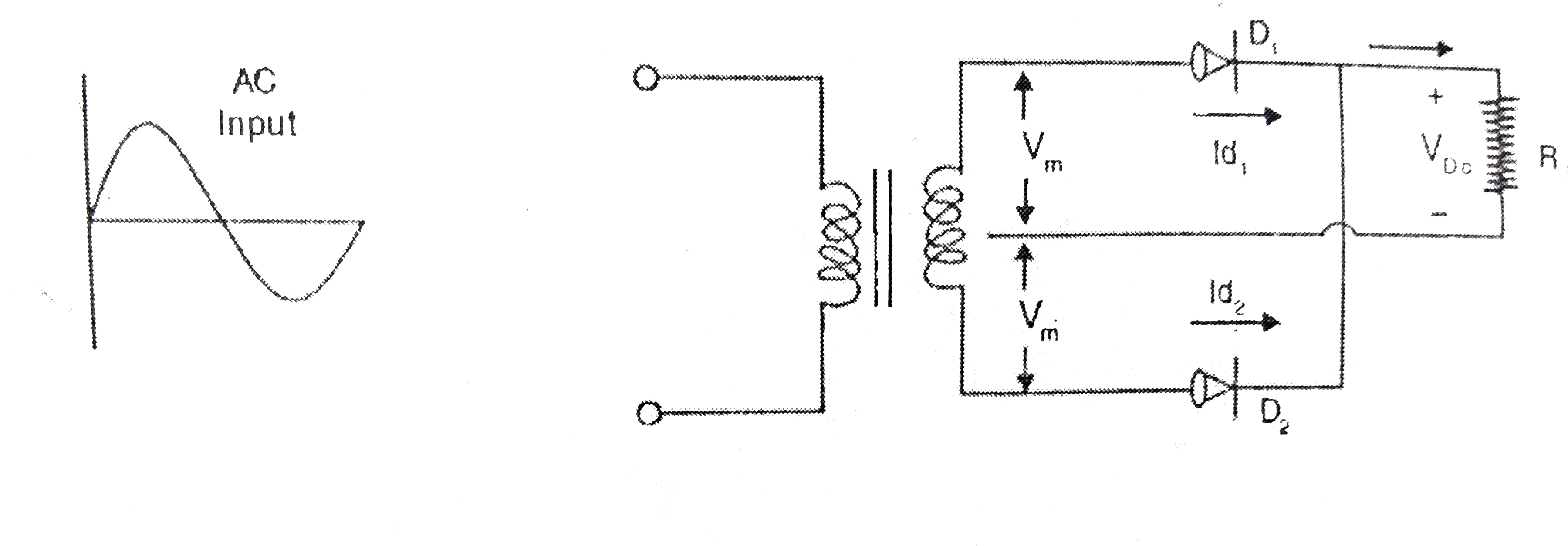
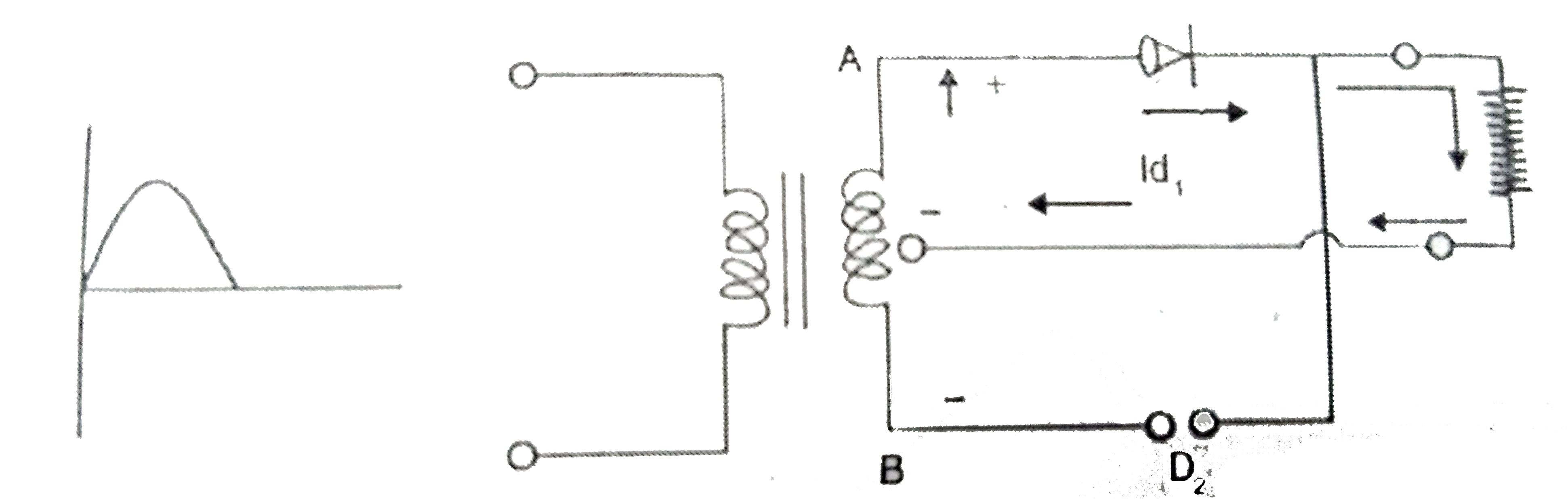
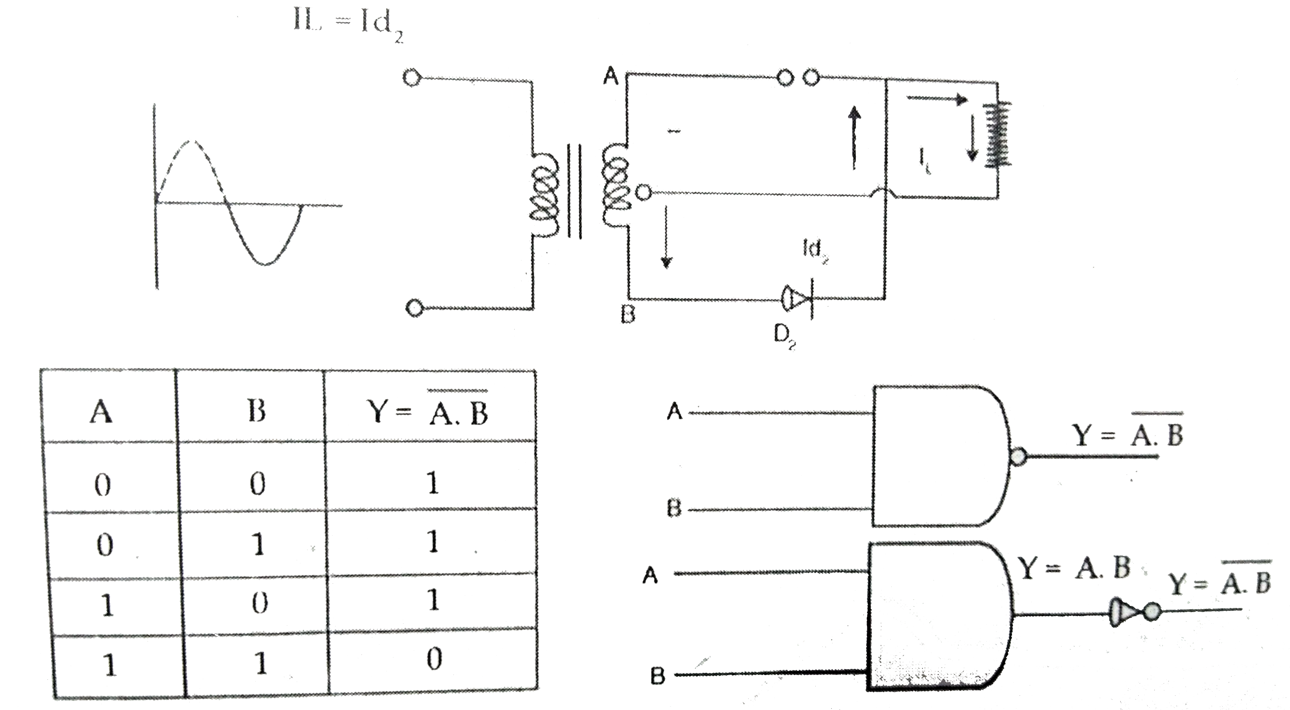
- (a) Students wants to use tow p-m jusnction diodes to convnet alternat...
Text Solution
|
- Draw the typical input and output characterisitics of an n-p-n trans...
Text Solution
|
- (a) Give three reasons why modulation of a message signal is necess...
Text Solution
|