Home
Class 10
PHYSICS
A child has drawn the electric circuit t...

A child has drawn the electric circuit to study Ohm's law as shown in (Fig. 3.42). His teacher told him that the circuit diagram needs correction. Study the circuit diagram and redraw it after making all corrections.
.

Text Solution

Verified by Experts

The circuit diagram is not correct because of following reasons
(i) Ammeter is connected in parallel with R and voltmeter connected in series with it in contrary of the fact that ammeter should be connected in series and voltmeter in parallel. This is so because same current flows in series and same voltage exist in parallel combination.
(ii) The current is drawn negative terminal and enter into the battery at possible terminal which is not possible in one battery circuit.
(iii) Cells are not connected in series combination in the battery of the circuit.
The correct diagram is as follow
Promotional Banner

Topper's Solved these Questions

  • ELECTRICITY

    NCERT EXEMPLAR ENGLISH|Exercise Short Answer Type Questions|17 Videos
  • LIGHT : REFLECTION AND REFRACTION

    NCERT EXEMPLAR ENGLISH|Exercise Long Answer Type Questions|9 Videos

Similar Questions

Explore conceptually related problems

Study the following circuit diagram and mark the correct options.

Study the following circuit diagram in fig. 5.320 and mark the correct options.

The correct Boolean operation represented by the circuit diagram drawn is

In the electric circuit shown in Fig., label the parts A, B, C, D, E, and E State the function of each part. Show in the diagram the direction of flow of current.

In the electric circuit shown in Fig. 1, label the parts A, B, C, D, E, and F State the function of each part. Show in the diagram the direction of flow of current.

To study the dependence of potential difference (V) on current I across Resistor (R), Four circuit diagrams are prepared. (i) Select the circuit diagrams which are correct. (ii) Give reason for the circuit diagrams which are not correct.

In the circuit diagram shown in figure, initially switch S is opened and the circuit is in steady state. At time t=0, the switch S is closed and the new steady state is reached after some time. Choose the correct option(s)

Consider the potentiomter circuit diagram as shown in the figure. If the potentiometer wire BD has net resistance of 15Omega, the choose the correct statement

Consider the circuit arrangnent shown in Fig. for studying input and output characteristics of npn transistor in CE configuration. Select the values of R_ and R_ for a transistor whose V_(BE)=0.7V , so that the transistor is operating at point Q as shown in the characteristics shown in Fig. Given that the input impedance of the transistor is very small and V_(C C)=V_(BB)=16V , also find the voltage gain and power gain of circuit making appropriate assumptions.

Study the diagram below and (i) Identify the electrical components labeled A,B, and C (ii) State whether the circuit given below is open or closed.

NCERT EXEMPLAR ENGLISH-ELECTRICITY-Short Answer Type Questions
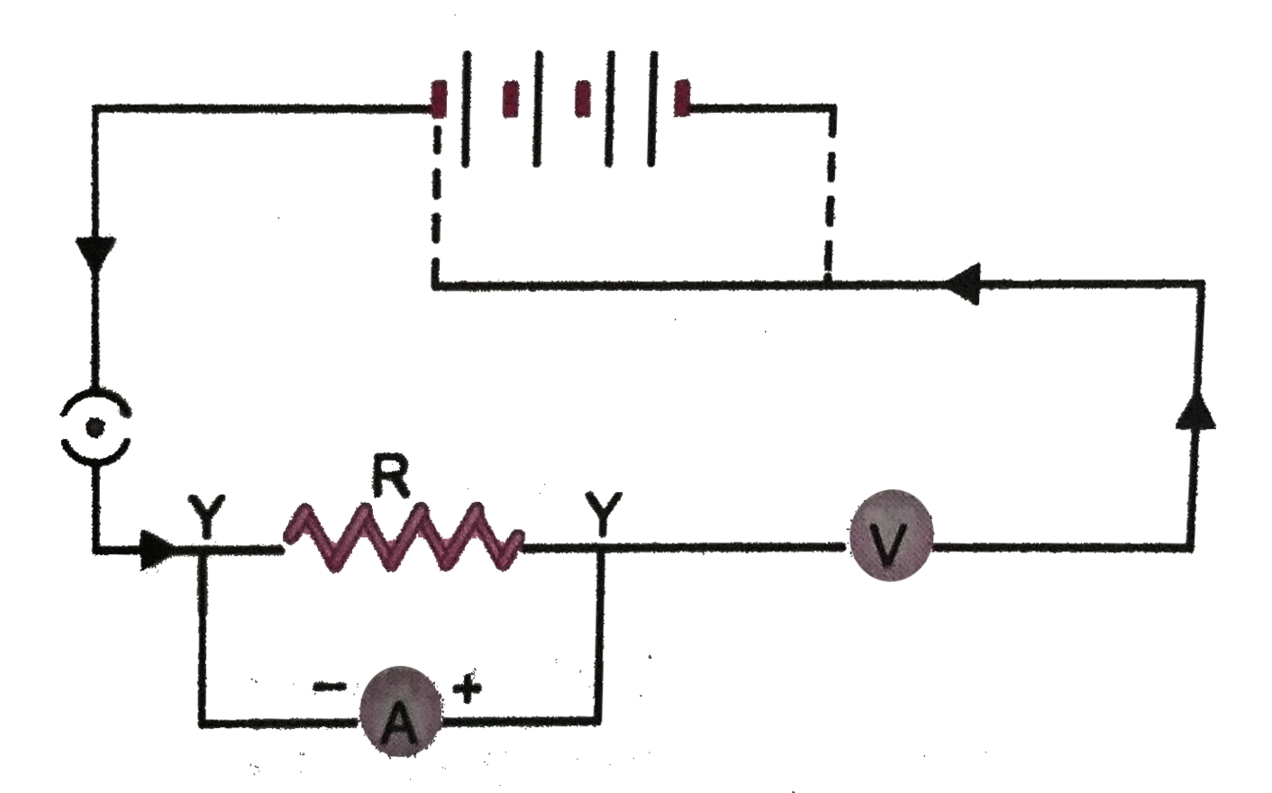
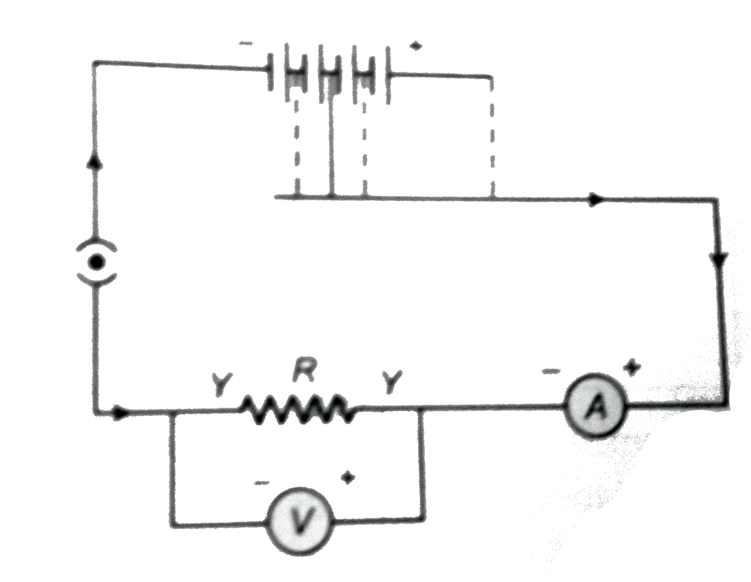
  1. A child has drawn the electric circuit to study Ohm's law as shown in ...

    Text Solution

    |

  2. Three 2 Omega resistors, A, B and C are connected as shown in figure. ...

    Text Solution

    |

  3. Should the resistance of an ammeter be low or high ? Give reason.

    Text Solution

    |

  4. Draw a circuit diagram of an electric circuit containing a cell, a key...

    Text Solution

    |

  5. How does use of a fuse-wire protect electrical appliances ?

    Text Solution

    |

  6. What is electrical resistivity ? In a series electrical circuit compri...

    Text Solution

    |

  7. What is the commercial unit of electrical energy ? Represent it in ter...

    Text Solution

    |

  8. (a) A current of 1 A flows in a series curcuit containing an electric ...

    Text Solution

    |

  9. Why is parallel arrangement used in domestic wiring ?

    Text Solution

    |

  10. B1,B2 and B3 are three identical bulbs connected as shown in (fig. 3.4...

    Text Solution

    |

  11. Three incandecent bulbs of 100 W each are connected in series in an el...

    Text Solution

    |

  12. State Ohm's law ? How can it be verified experimentally ? Does it hold...

    Text Solution

    |

  13. What is electrical resistivity ? How does it depend om temperature. Gi...

    Text Solution

    |

  14. How will you infer with the help of an experiment that the same curren...

    Text Solution

    |

  15. How will you conclude that the same potential difference (voltage) exi...

    Text Solution

    |

  16. What is Joule's heating effect ? How can it be demonstrated experiment...

    Text Solution

    |

  17. Find out the folowing in the electric circuit given in (Fig. 3.48). ...

    Text Solution

    |