Home
Class 12
PHYSICS
Draw the circuit diagram of a common emi...

Draw the circuit diagram of a common emitter transistor amplifier. Write the expression for its voltage gain. Explain , how the input and output signal differ in phase by `180^(@)`

Text Solution

Verified by Experts


During positive half cycle of input single, forward bias of `E_(B)` junction decreases casuing. `I_(e)` and hence `I_(c)` decreases. It results in voltage drop across load resistance `R_(L)`. So, from the relation.
`V_(CE) = V_("CC") - I_(C) R_(L), V_(0)` increases.
As collector is connected to the negative terminal of battery, increase in collector voltage indicates that collector becomes more negative. As in common ammeter amplifier, the output voltage decreases with increases in input signal and increases with decreasing input signal, so both input and output signals are out of phase with phase difference `pi`. During negative half cycle of input signal, the forward bias of `E_(B)` junction decreases. As a result, `I_(E)` and hence `I_(C)` decreases. Voltage Drop across `R_(L) = I_(C)R_(L)` also decreases. So, the output voltage increases. As collector is connected to the positive terminal of `V_("CC")`, so, increase in `V_(0) rArr` collector voltage will be more positive. An amplified positive signal is obtained across the output.
Promotional Banner

Topper's Solved these Questions

  • XII BOARDS

    XII BOARD PREVIOUS YEAR PAPER ENGLISH|Exercise PHYSICS (Theory) DELHI BOARD -2016 [SET -I][COMPTT.]|11 Videos
  • XII BOARDS

    XII BOARD PREVIOUS YEAR PAPER ENGLISH|Exercise C.B.S.E.CLASS-XII PHYSICS (THEORY) [SET-I] (SECTION-A)|5 Videos
  • XII BOARDS

    XII BOARD PREVIOUS YEAR PAPER ENGLISH|Exercise SECTION-B|52 Videos
  • SAMPLE PAPER 2019

    XII BOARD PREVIOUS YEAR PAPER ENGLISH|Exercise SECTION D|6 Videos

Similar Questions

Explore conceptually related problems

Draw the labelled circuit diagram of a common-emitter transistor amplifier : Explain clearly how the input and output signals are in opposite phase.

Draw a circuit diagram of C.E. transistor amplifier. Briefly explain its working and write the expression for (i) current gain (ii) voltage gain of the amplifier.

For a common-emitter transistor amplifier, the current gain is 60. If the emitter current is 6.6 mA then its base current is

Give a circuit diagram of a common emitter amplifier using an n-p-n transistor. Draw the input and output wavefroms of the signal. Write the expression for its voltage gain.

In a common emitter amplifier, the input and output voltage are out of phase by

Draw a labelled circuit diagram of a transistor acting as a common emitter amplifier. What is meant by phase reversal?

The input resistance of a common emitter transistor amplifier, if the output resistance is 500 kOmega , the current gain alpha=0.98 and the power gain is 6.0625 xx 10^(6) is

In a common emitter amplifier circuit using an n-p-n transistor, the phase difference between the input and the output voltages will be:-

Draw a labelled circuit diagram of n - p - n germanium transistor in common emitter configuration. Explain briefly, how this transistor is used as a voltage amplifier.

XII BOARD PREVIOUS YEAR PAPER ENGLISH-XII BOARDS-SECTION-C
  1. Draw the pattern of magnetic field lines for a circular coil carrying ...

    Text Solution

    |

  2. State the reason, why the photodiode is always operated under reverse ...

    Text Solution

    |

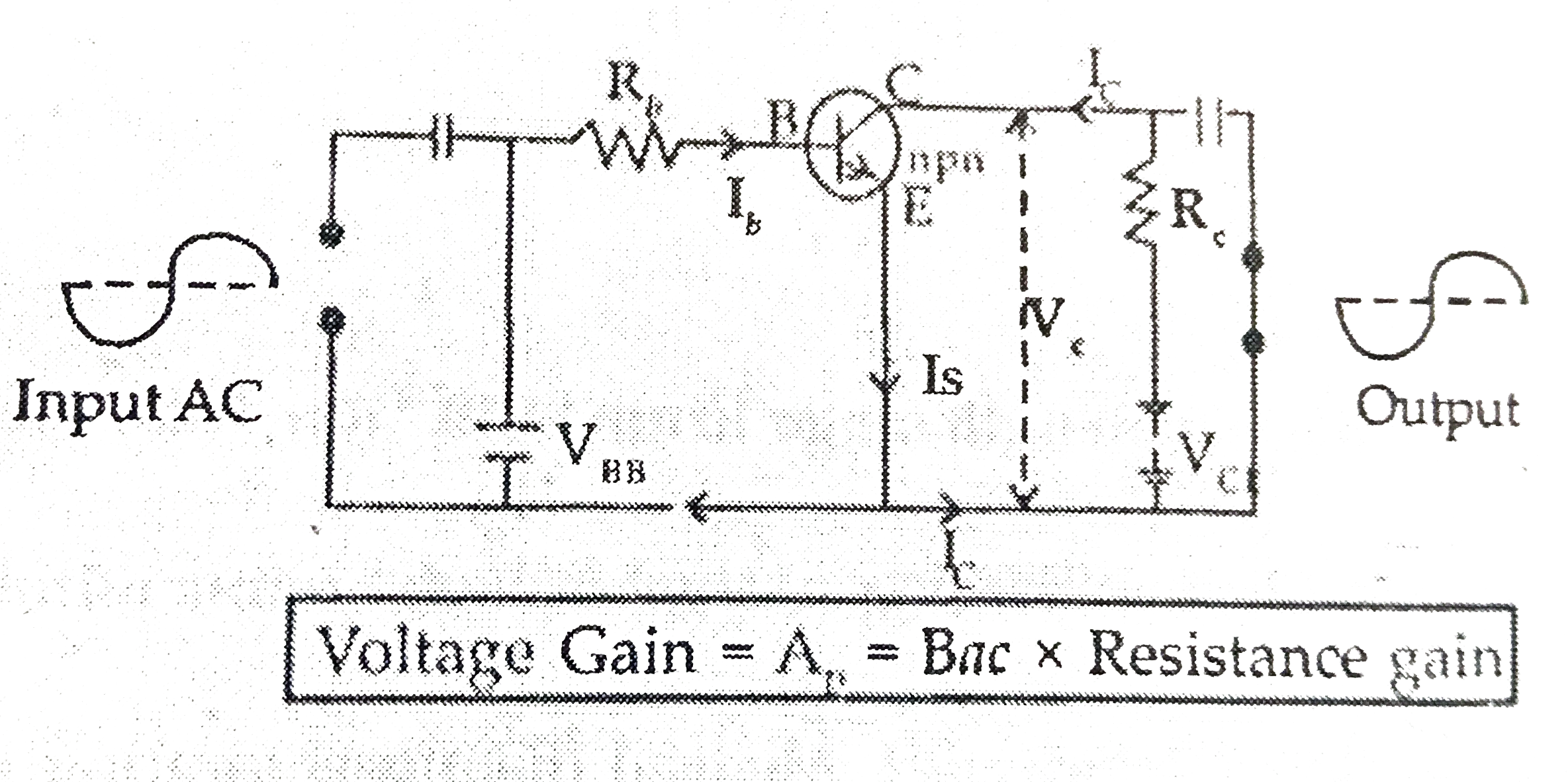
  3. Draw the circuit diagram of a common emitter transistor amplifier. Wri...

    Text Solution

    |

  4. Draw a circuit diagram of a full-wave rectifier. Explain its working p...

    Text Solution

    |

  5. Briefly explain the three factors which justify the need of modulating...

    Text Solution

    |

  6. The current through two inductors of self inductance 12 mH and 30 mH i...

    Text Solution

    |

  7. Two wavelengths of sodium light 590 nm and 596 nm are used in turn to ...

    Text Solution

    |

  8. (a) Draw the equipotential surfaces corresponding to a uniform electri...

    Text Solution

    |

  9. Identiy the part of the electromagnatic spectrum used in (i) radar and...

    Text Solution

    |

  10. Define the term wavefront. Using Huygens' wave theory, verify the laws...

    Text Solution

    |

  11. Define term, "refreactive index " of a medium.

    Text Solution

    |

  12. (a) Derive the expression for the torque acting on a current carrying ...

    Text Solution

    |

  13. A giant refracting telescope at an observatory has an objective lens o...

    Text Solution

    |

  14. (a) State Gauss's law for magnetism. Explain its significance. (b) ...

    Text Solution

    |

  15. Write three points of differences between para, dia-and ferro- mangeti...

    Text Solution

    |

  16. Define the term 'decay constant' of a radioactive sample. The disinteg...

    Text Solution

    |

  17. Three photo diodes D1, D2, and D3 are made of semiconductors having ba...

    Text Solution

    |

  18. Describe briefly the functions of the three segments of n-p-n transist...

    Text Solution

    |

  19. Draw a circuit diagram of a full-wave rectifier. Explain its working p...

    Text Solution

    |

  20. A message signal of frequency 20 kHz and peak voltage 10 V is used to ...

    Text Solution

    |