A
B
C
D
Text Solution
Verified by Experts
The correct Answer is:


Topper's Solved these Questions
ELECTRICITY
KUMAR PRAKASHAN|Exercise OBJECTIVE QUESTIONS AND ANSWERS (Answer the following questions as directed (Miscellaneous):)|53 VideosELECTRICITY
KUMAR PRAKASHAN|Exercise VALUE BASED QUESTIN WITH ANSWERS|15 VideosELECTRICITY
KUMAR PRAKASHAN|Exercise OBJECTIVE QUESTIONS AND ANSWERS (Match the following:)|3 VideosMAGNETIC EFFECTS OF ELECTRIC CURRENT
KUMAR PRAKASHAN|Exercise VALUE BASED QUESTIONS WITH ANSWERS|15 Videos
Similar Questions
Explore conceptually related problems
KUMAR PRAKASHAN-ELECTRICITY-OBJECTIVE QUESTIONS AND ANSWERS (Choose the correct option from those given below each question: )
- Which of the following options is not the formula for heat energy (in ...
Text Solution
|
- Which option is correct for the following statements A and B? State...
Text Solution
|
- In which of the following circuits the voltmeter and ammeter are conne...
Text Solution
|
- Maximum 1 A current can pass through a bulb haVing resistance 100 Omeg...
Text Solution
|
- Which of the following is not a unit of electric energy?
Text Solution
|
- Of which physical quantity is the unit,.VA. ?
Text Solution
|
- Which of the following circuit symbols is used to represent an electr...
Text Solution
|
- The resistance of 300 m long wire with cross-sectional area 10^(-6)m^2...
Text Solution
|
- What will be the equivalent resistance of the following circuit?
Text Solution
|
- Three resistors of resistances 2 Omega, 3 Omega and 5 Omega are connec...
Text Solution
|
- An electric iron of power 2 kW is used for 3 hours. At Rs 5 per unit, ...
Text Solution
|
- The working of electric fuse is based on the ...
Text Solution
|
- Resistivity of a material depends on ......... of the material.
Text Solution
|
- When resistors of resistances R1 and R2 (R2 lt R1) are connected in pa...
Text Solution
|
- When resistors of resistances R1 and R2 (R2 gt R1) are connected in se...
Text Solution
|
- In the following circuit, which electric component is connected in a w...
Text Solution
|
- 1 C = ......... muC
Text Solution
|
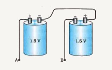
- Connection of two cells of 1.5 V is shown in the following figure: ...
Text Solution
|
- The following figure shows the V - I graph for four different resistor...
Text Solution
|
- A potential difference of 100 V is applied across an electric bulb mar...
Text Solution
|