Home
Class 11
PHYSICS
Two capacitros of capacity 6 mu F are ch...

Two capacitros of capacity `6 mu F` are charged to 100 V and 50 V separately and connected as shown. Now all the three switches `S_(1), S_(2)` and `S_(3)` are closed.

Suppose `q_(1), q_(2)` and `q_(3)` be the magnitudes of charge flown from switches `S_(1), S_(2)` and `S_(3)` after they closed. Then

A

`q_(1) = q_(3)` and `q_(2) = 0`

B

`q_(1) = q_(3) = (q_(2))/(2)`

C

`q_(1) = q_(3) = 2q_(2)`

D

`q_(1) = q_(2) = q_(3)`

Text Solution

Verified by Experts

The correct Answer is:
D
Promotional Banner

Topper's Solved these Questions

  • ELECTROSTATICS

    DC PANDEY ENGLISH|Exercise Matrix Matching|2 Videos
  • ELECTROSTATICS

    DC PANDEY ENGLISH|Exercise Integer|17 Videos
  • ELECTROSTATICS

    DC PANDEY ENGLISH|Exercise JEE Advanced|44 Videos
  • ELASTICITY

    DC PANDEY ENGLISH|Exercise Medical entrances s gallery|21 Videos
  • EXPERIMENTS

    DC PANDEY ENGLISH|Exercise Subjective|15 Videos

Similar Questions

Explore conceptually related problems

Two capacitors of capacity 6 muF and 3 muF are charge 100 V and 50 V separately and connected as shown in Now all the three switches S_(1), S_(2) , and S_(3) are closed. Which plates form an isolated system?

Two capacitros of capacity 6 and 3 mu F are charged to 100 V and 50 V separately and connected as shown. Now all the three switches S_(1), S_(2) and S_(3) are closed. Charges on both the capacitors in steady state will be (on 6 mu F first)

Two capacitors of capacity 6 muF and 3 muF are charge 100 V and 50 V separately and connected as shown in figure. Now all the three switches S_(1),S_(2) , and S_(3) are closed. Charge on the 3 muF capacitor in steady state willl be.

Two capacitors of capacity 6 muF and 3 muF are charge 100 V and 50 V separately and connected as shown in (Fig.4.201.) Now all the three switches S_(1),S_(2) , and S_(3) are closed. Charge on the 6 muF capacitor in steady state will be.

Two capacitors C_(1) and C_(2) are charged to same potential V , but with opposite polarity as shown in the figure. The switches S_(1) and S_(2) are then closed

Two capacitors C_(1) = 4 muF and C_(2) = 2muF are charged to same potential V = 500 Volt, but with opposite polarity as shown in the figure. The switches S_(1) and S_(2) are closed.

(i) In an isolated system (neither connected to the terminal of a battery nor to any other source of charge e.g each) net charge remains constant. (ii) From two terminal of a battery or from two plates of a capacitor equal and opposite charges enter or leave. Question : Two capacitors of capacity 6muF and 3muF are charged to 100 V and 50 V separatelly and connected as shown. Now all the three swiches S_(1)S_(2) and S_3 are closed. Which plate (s) form an isolated system .

Find the charge flown when the switch S is closed.

Two capacitors C_(1) = 2mu F and C_(2) = 1 muF are charged to same potential V = 100 V , but with opposite polarity as shown in the figure. The switches S_(1) and S_(2) are closed. The ratio of final energy to the initial energy of the system is

Four capacitors of capacitance 10 mu F and a battery of 2V are arranged as shown. How much mu C charge will flow through AB after the switch S is closed ?

DC PANDEY ENGLISH-ELECTROSTATICS-Comprehension
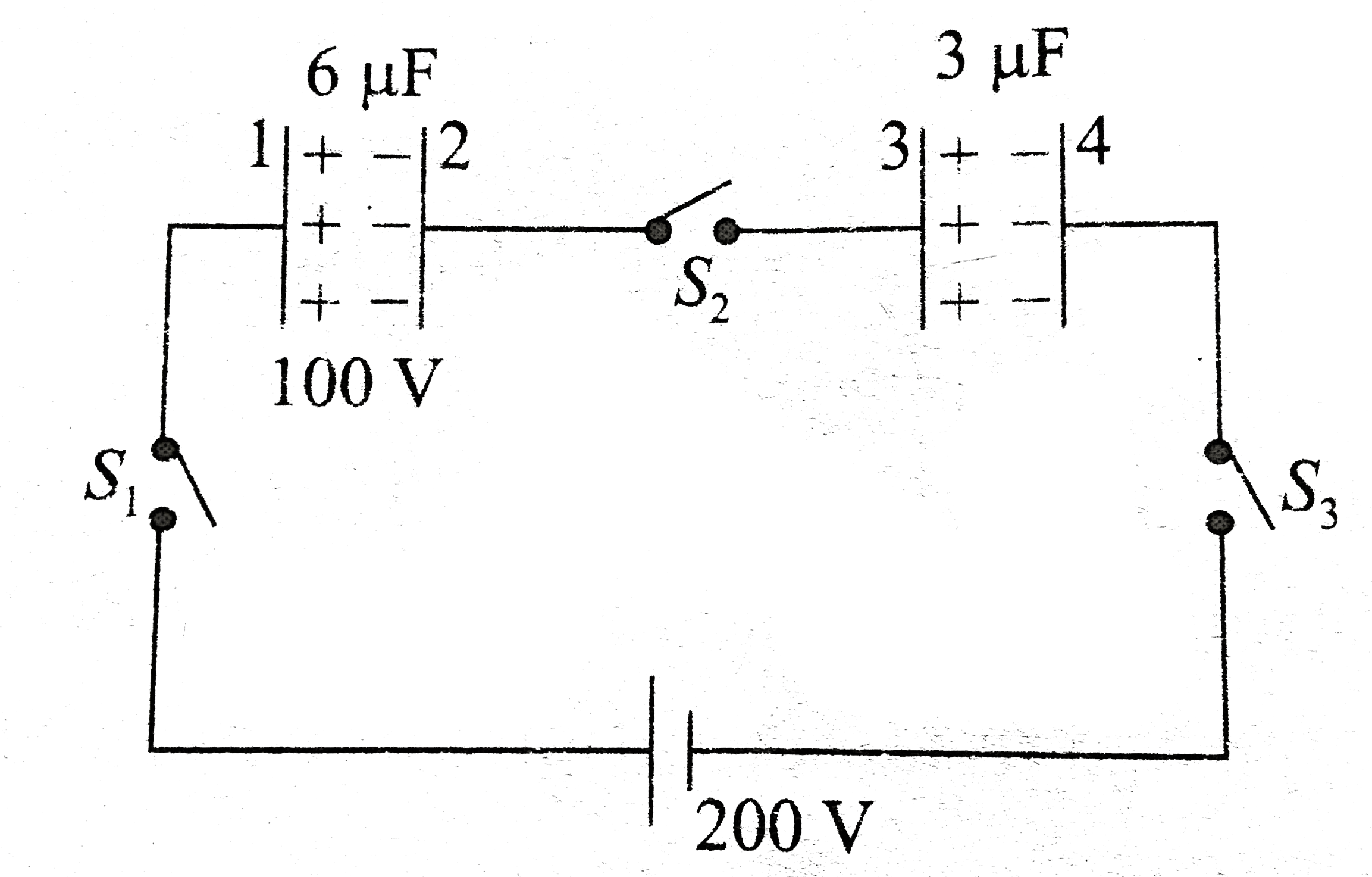
  1. Two capacitors of capacity 6 muF and 3 muF are charge 100 V and 50 V s...

    Text Solution

    |

  2. Two capacitros of capacity 6 and 3 mu F are charged to 100 V and 50 V ...

    Text Solution

    |

  3. Two capacitros of capacity 6 mu F are charged to 100 V and 50 V separa...

    Text Solution

    |

  4. A charge q = (-2 xx 10^(-9)) is placed at (1 m, 2m, 3m). There is a po...

    Text Solution

    |

  5. A charge q = (-2 x 10^(-9)) is placed at (1 m, 2m, 3m). There is a poi...

    Text Solution

    |

  6. Electric potential is a scalar quantity. Due to a point charge charge ...

    Text Solution

    |

  7. Electric potential is a scalar quantity. Due to a point charge charge ...

    Text Solution

    |

  8. A capacitor is connected to a variable source of potential. Current fl...

    Text Solution

    |

  9. A capacitor is connected to a variable source of potential. Current fl...

    Text Solution

    |

  10. When two concentric shells are connected by a thin conducting wire, wh...

    Text Solution

    |

  11. When two concentric shells are connected by a thin conducting wire, wh...

    Text Solution

    |

  12. In C - R circuit, answer the following two questions During charging...

    Text Solution

    |

  13. In C - R circuit, answer the following two questions Dielectric cons...

    Text Solution

    |

  14. In the figure m(A) = m(B) = 1 kg. Block A is neutral while q(B) = -1C....

    Text Solution

    |

  15. In the figure m(A) = m(B) = 1 kg. Block A is neutral while q(B) = -1C....

    Text Solution

    |

  16. In the figure m(A) = m(B) = 1 kg. Block A is neutral while q(B) = -1C....

    Text Solution

    |

  17. A solid conducting sphere of radius 'a' is surrounded by a thin unchar...

    Text Solution

    |

  18. A solid conducting sphere of radius 'a' is surrounded by a thin unchar...

    Text Solution

    |

  19. A solid conducting sphere of radius 'a' is surrounded by a thin unchar...

    Text Solution

    |

  20. Capacitor C(3) in the circuit is a veriable capacitor (its capacitance...

    Text Solution

    |