Home
Class 11
PHYSICS
In the circuit as shown in the figure th...

In the circuit as shown in the figure the effective capacitance between `A` and `B` is

Text Solution

Verified by Experts

The correct Answer is:
4
Promotional Banner

Topper's Solved these Questions

  • ELECTROSTATICS

    DC PANDEY ENGLISH|Exercise Matrix Matching|2 Videos
  • ELASTICITY

    DC PANDEY ENGLISH|Exercise Medical entrances s gallery|21 Videos
  • EXPERIMENTS

    DC PANDEY ENGLISH|Exercise Subjective|15 Videos

Similar Questions

Explore conceptually related problems

Thirteen resistances each of resistance R ohm are connected in the circuit as shown in the figure below. The effective resistance between A and B is

Thirteen resistances each of resistance R ohm are connected in the circuit as shown in the figure below. The effective resistance between A and B is

Thirteen resistances each of resistance R ohm are connected in the circuit as shown in the figure below. The effective resistance between A and B is

Four capacitors are connected in a circuit as shown in the figure. The effective capacitance in muF between points A and B will be

Consider an infinite matrix of capacitors as shown in the figure. The effective capacitance between point A and B will be

In this figure the equivalent capacitance between A and B will be

Six equal capacitors each of capacitance 10muF are connect as shown in the figure. Then the equivalent capacitance between A and B is

An infinite number of identical capacitors each of capacitance 1 mF are connected as shown in the figure. Then the equivalent capacitance between A and B is. .

An infinite number of identical capacitors each of capacitance 1 mF are connected as shown in the figure. Then the equivalent capacitance between A and B is. .

In the given circuit the effective capacity between A and B is

DC PANDEY ENGLISH-ELECTROSTATICS-Integer
  1. The centres of two identical small conducting sphere are 1 m apart. Th...

    Text Solution

    |

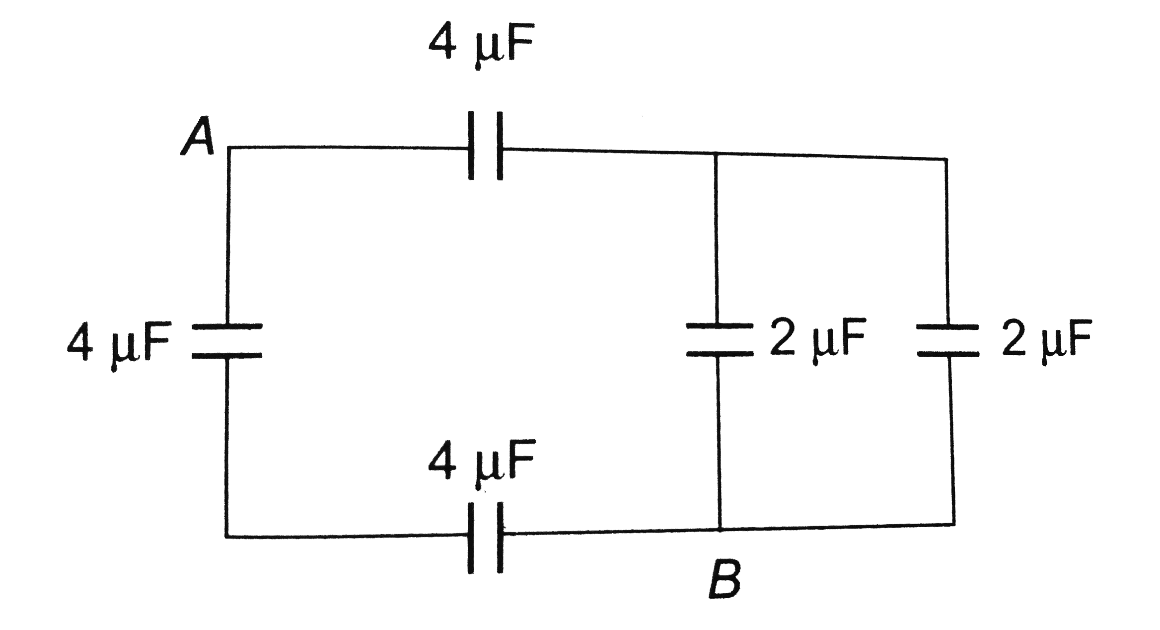
  2. In the circuit as shown in the figure the effective capacitance betwee...

    Text Solution

    |

  3. A 2 mu F condenser is charged upto 200 volt and then battery is remove...

    Text Solution

    |

  4. A hollow sphere of radius 2R is charged to V volts and another smaller...

    Text Solution

    |

  5. Consider the circuit shown in the figure. Capacitors A and B, each hav...

    Text Solution

    |

  6. Four point charge q, - q, 2Q and Q are placed in order at the corners ...

    Text Solution

    |

  7. Two point charge q(1)=2muC and q(2)=1muC are placed at distance b=1 an...

    Text Solution

    |

  8. Two identical charges are placed at the two corners of an equilateral ...

    Text Solution

    |

  9. There are four concentric shells A,B, C and D of radii a,2a,3a and 4a ...

    Text Solution

    |

  10. A solid conducting sphere of radius a having a charge q is surrounde...

    Text Solution

    |

  11. Electric field at the centre of uniformly charge hemispherical shell o...

    Text Solution

    |

  12. In the circuit given below, the charge in muC, on the capacitor having...

    Text Solution

    |

  13. A parallel plate capacitor is connected to a battery of emf V volts. N...

    Text Solution

    |

  14. Four identical metal plates are arranged as shown plates 1 and 4 are c...

    Text Solution

    |

  15. Four identical positive point charges Q are fixed at the four corners ...

    Text Solution

    |

  16. There is an infinite line of uniform linear density of charge +lamda. ...

    Text Solution

    |

  17. Two identical capacitors haveng plate separation d(0) are connected pa...

    Text Solution

    |