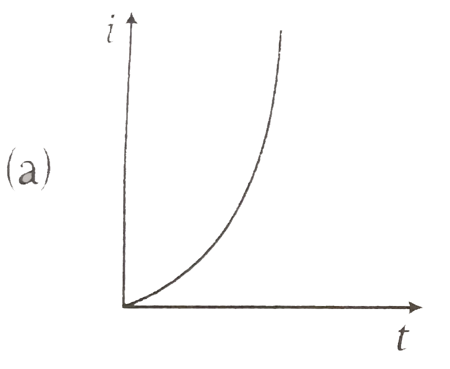
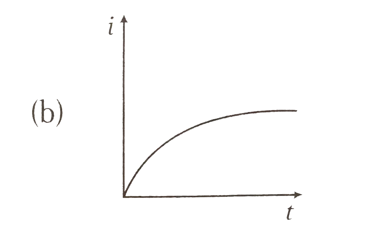
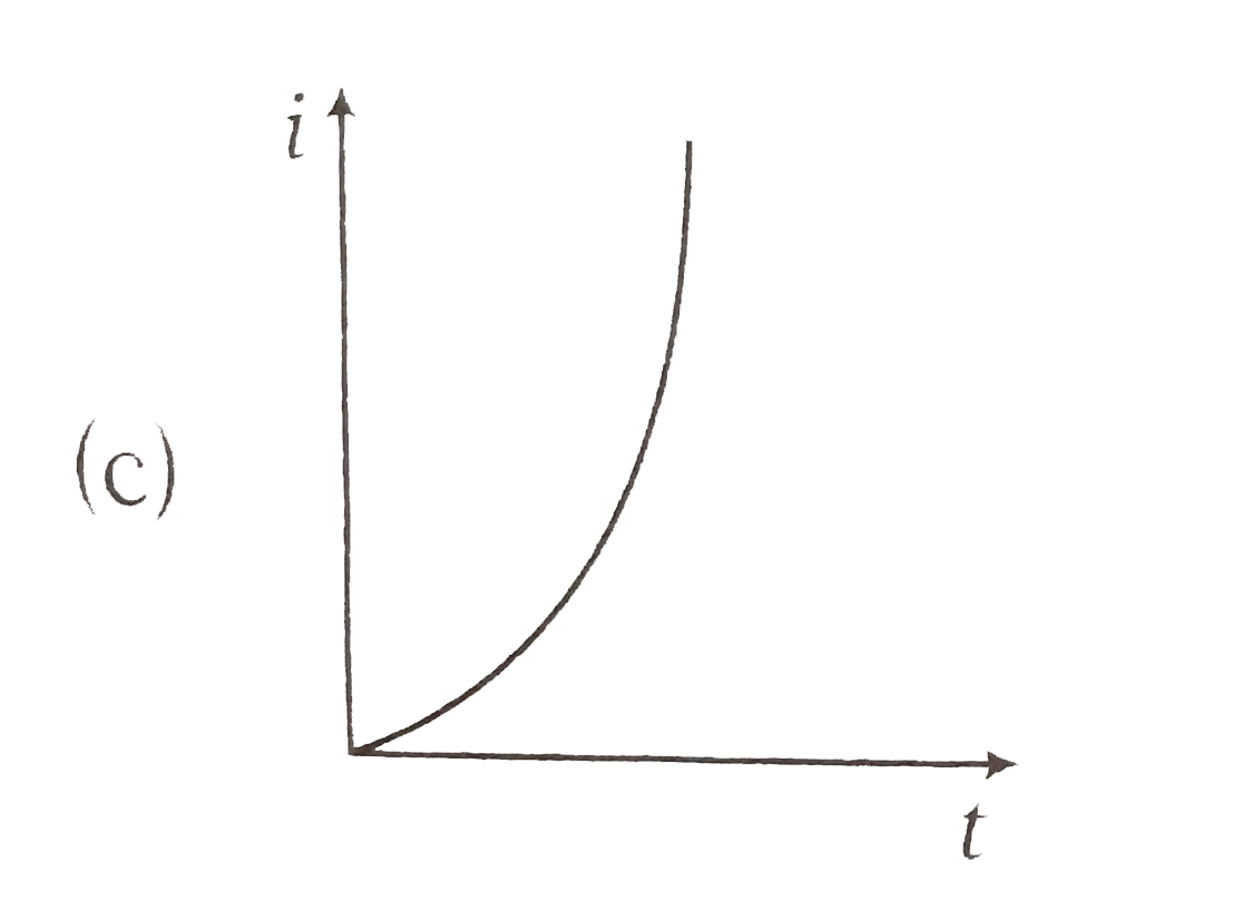
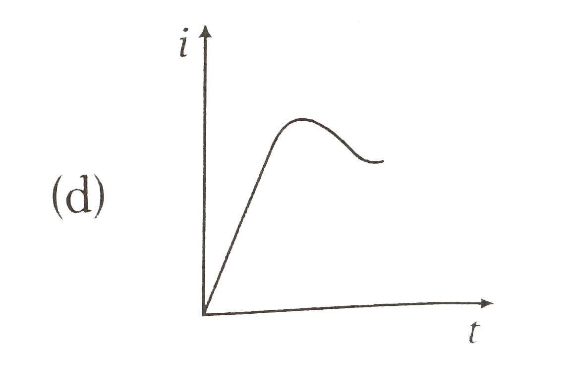
Home
Class 12
PHYSICS
When a battery is connected across a ser...

When a battery is connected across a series combination of self inductance L and resistance R , the variation in the current i with time t is best represented by

A

B

C

D

Text Solution

AI Generated Solution

The correct Answer is:
To solve the problem of how the current \( i \) varies with time \( t \) when a battery is connected across a series combination of self-inductance \( L \) and resistance \( R \), we can follow these steps: ### Step 1: Understand the Circuit When a battery is connected to a series circuit consisting of a resistor \( R \) and an inductor \( L \), the current does not instantly reach its maximum value. Instead, it increases gradually over time due to the inductance. ### Step 2: Write the Current Equation The current \( i(t) \) in an LR circuit can be described by the equation: \[ i(t) = I_{\text{max}} \left(1 - e^{-\frac{t}{\tau}}\right) \] where: - \( I_{\text{max}} = \frac{E}{R} \) (the maximum current, where \( E \) is the emf of the battery), - \( \tau = \frac{L}{R} \) (the time constant of the circuit). ### Step 3: Analyze the Current at Specific Times - At \( t = 0 \): \[ i(0) = I_{\text{max}} \left(1 - e^{0}\right) = I_{\text{max}} \cdot 0 = 0 \] This indicates that the current starts at zero when the switch is first closed. - At \( t \to \infty \): \[ i(\infty) = I_{\text{max}} \left(1 - e^{-\infty}\right) = I_{\text{max}} \cdot 1 = I_{\text{max}} \] This shows that the current approaches its maximum value as time goes on. ### Step 4: Graphical Representation The equation \( i(t) = I_{\text{max}} \left(1 - e^{-\frac{t}{\tau}}\right) \) describes an exponential rise. The graph starts at zero when \( t = 0 \) and asymptotically approaches \( I_{\text{max}} \) as \( t \) increases. ### Step 5: Identify the Correct Option Based on the description of the current's behavior over time, the correct graphical representation is an exponential curve that starts at zero and rises towards \( I_{\text{max}} \). This matches option B. ### Conclusion The variation in the current \( i \) with time \( t \) when a battery is connected across a series combination of self-inductance \( L \) and resistance \( R \) is best represented by option B. ---

To solve the problem of how the current \( i \) varies with time \( t \) when a battery is connected across a series combination of self-inductance \( L \) and resistance \( R \), we can follow these steps: ### Step 1: Understand the Circuit When a battery is connected to a series circuit consisting of a resistor \( R \) and an inductor \( L \), the current does not instantly reach its maximum value. Instead, it increases gradually over time due to the inductance. ### Step 2: Write the Current Equation The current \( i(t) \) in an LR circuit can be described by the equation: \[ ...
Promotional Banner

Topper's Solved these Questions

  • ELECTROMAGNETIC INDUCTION

    DC PANDEY ENGLISH|Exercise Medical entrance special format questions|17 Videos
  • ELECTROMAGNETIC INDUCTION

    DC PANDEY ENGLISH|Exercise Match the columns|5 Videos
  • ELECTROMAGNETIC INDUCTION

    DC PANDEY ENGLISH|Exercise Check point|60 Videos
  • CURRENT ELECTRICITY

    DC PANDEY ENGLISH|Exercise Medical entrances gallery|97 Videos
  • ELECTROMAGNETIC WAVES

    DC PANDEY ENGLISH|Exercise Sec C|22 Videos

Similar Questions

Explore conceptually related problems

A sinusoidal voltage Vsin(at) is applied across a series combination of resistance R and inductor L. The amplitude of the current in the circuit is

A cell of e.m.f E and internal resitance r ,is connected to an external resistance R. the variation of potential difference V across the resistance R as function of R as shown in the figure, is the best represented by curve

A circuit consisting of a constant EMF E, a self-inductance L and a resistance R in sereis is closed at time t=0 . The relation between the current i in the circuit and the time t is as shown by the curve. A in the figure-5.321. when one or more of parameters E,R and L are changed, the curve B is obtained. Then it is possible that:

When a battery connected across a resistor of 16 Omega , the voltage across the resistor is 12 V. When the same battery is connected across a resistor of 10 Omega , voltage across it is 11 V. The internal resistance of the battery (in ohm) is

A battery of emf E and internal resistance r is connected across a resistance R. Resistance R can be adjusted to any value greater than or equal to zero. A graph is plotted between the current passing through the resistance (I) and potential difference across the termainals of the battery (V). Maximum power developed across the resistance R is

Four equal resistance dissipated 5 W of power together when connected in series to a battery of negligible internal resistance . The total power dissipated in these resistance when connected in parallel across the same battery would be .

A battery of emf epsilon and internal resistance r is connected across a load resistance R_L . The plot between output power and load resistance is shown in the figure. The value of emf epsilon and internal resistance r respectively will

cells each of emf e and internal resistance r are joined in series to form a row and such rows are connected in parallel to form a battery of N = mn cells. If this battery is connected to an external resistance R . Show that current f flowing through the external resistance R is given by : I=(Ne)/(mR+nr)

An inductor 20xx10^(-3) a capacitor 100(mu)F and a resistor 50 Omega are connected in series across a source of emf V=10 sin 314 t . If resistance is removed from the circuit and the value of inductance is doubled, the variation of current with time in the new circuit is

A battery of emf E and internal resistance r is connected across a resistance R. Resistance R can be adjusted to any value greater then or equla to zero. A graph is plotted between the current passing through the resistance (I) and potential (V) across it. Select the correct alternatives.

DC PANDEY ENGLISH-ELECTROMAGNETIC INDUCTION-Taking it together
  1. The variation of induced emf (epsilon ) with time (t) in a coil if a s...

    Text Solution

    |

  2. The current i in an inductionn coil varies with time t according to th...

    Text Solution

    |

  3. When a battery is connected across a series combination of self induct...

    Text Solution

    |

  4. In the circuit shown in the figure, the jockey J is being pulled towar...

    Text Solution

    |

  5. The value of time constant for the given circuit is

    Text Solution

    |

  6. A infinitely long conductor AB lies along the axis of a circular loop ...

    Text Solution

    |

  7. A physicist works in a laboratory where the magnetic field is 2T. She ...

    Text Solution

    |

  8. A wheel with ten metallic spokes each 0.50 m long is rotated with a sp...

    Text Solution

    |

  9. An aeroplane in which the distance between the tips of wings is 50 m i...

    Text Solution

    |

  10. A conducting square loop of side l and resistance R moves in its plane...

    Text Solution

    |

  11. Two rails of a railway track, insulated from each other and the ground...

    Text Solution

    |

  12. A Pair of coils of turns n(1) and n(2) are kept close together. Curren...

    Text Solution

    |

  13. A loop made of straight edegs has six corners at A(0,0,0), B(L, O,0) C...

    Text Solution

    |

  14. One conducting U tube can slide inside another as shown in figure, mai...

    Text Solution

    |

  15. In a closed loop, which has some inductance but negligible resistance,...

    Text Solution

    |

  16. A magnetic field given by B(t) =0.2t-0.05t^(2) tesla is directed perpe...

    Text Solution

    |

  17. A small magnet M is allowed to fall through a fixed horizontal conduct...

    Text Solution

    |

  18. A rectangular loop with a sliding connector of length 10 cm is situate...

    Text Solution

    |

  19. When the current in the portion of the circuit shown in the figure is...

    Text Solution

    |

  20. Two different coils have self-inductance L(1)=8mH,L(2)=2mH. The curren...

    Text Solution

    |