Home
Class 12
PHYSICS
In the circuit shown , the emf of each b...

In the circuit shown , the emf of each battery is `60 V` and `C_(1)=2 muF` and `C_(2)=3 muF`. Find the charges that will flow through the sections `1 , 2` and `3` after the Key is closed.
.

Text Solution

Verified by Experts

The correct Answer is:
`120 muC`

when switch is opened, `2` and `3 muF` capatiors are in series. So,
`C_(eq)=(2xx3)/5=6/5 muF`
Hence, charge on each capacitor is
`q=CV=6/5xx90=108 muC`
.
When switch `S` is closed, let `q_(1)` and `q_(2)` be charge on the two capacitors as in (b). So ,
`q_(1)=2xx30=60 muC`
`q_(2)=3xx60=180 muC`
Let charge `q_(B)` goes to the upper plate of `3 muF` capacitor and lower plate of `2muF` capacitor. Initially, both the plates have charge `+q-q=0`. Finally, they have charges `q_(2)-q_(1)`. So,
`q_(2)-q_(1)=q_(B)+0`
or `q_(B)=q_(2)-q_(1)=180-60=120 muC`
Alternatively: After closing the switch, charge floeing out of `2 muF` capacitor is
`Deltaq_(2)=180-108-60=48 muC`
Charge flown into `3 muF` capacitor is
`Deltaq_(2)=180-108=72 muF`
So the net charge flown through the switch is
`Deltaq=Deltaq_(1)+Delta_(2)=48+72=120 muC`
which is same as `q_(B)` obtained earlier.
Promotional Banner

Topper's Solved these Questions

  • CAPACITOR AND CAPACITANCE

    CENGAGE PHYSICS ENGLISH|Exercise Single Correct|49 Videos
  • CAPACITOR AND CAPACITANCE

    CENGAGE PHYSICS ENGLISH|Exercise Multile Correct|11 Videos
  • CAPACITOR AND CAPACITANCE

    CENGAGE PHYSICS ENGLISH|Exercise Exercise 4.2|32 Videos
  • ATOMIC PHYSICS

    CENGAGE PHYSICS ENGLISH|Exercise ddp.4.3|15 Videos
  • CENGAGE PHYSICS DPP

    CENGAGE PHYSICS ENGLISH|Exercise subjective type|51 Videos

Similar Questions

Explore conceptually related problems

In the circuit shown, the emf of each battery is E. Find the charges that will flow when the switch S is closed, through sections 1, 2 and 3 in the directions indicated by the arrows.

In the circuit shown in figure, the ratio of charge on 5muF and 2muF capacitor is

In the circuit shown, all capacitors are initially uncharged. The capacitance of the capacitors are C_(1)=2muF and C_(2)=3muF The switch is closed at position 1 and kept closed until the current in the ideal ammeter becomes negligible. Which of the following statements is(are) true?

A circuit has section AB as shown in The emf of the cell is 10 V , and the capacitors have capacitances C_(1)=1 muF and C_(2)=2 muF . Find the voltage across each capacitor. .

Capacitor C_1 = 2 muF and C_2 = 3muF are connected in series to a battery of emf epsilon= 120 V whose midpoint is earthed. The wire connecting the capacitors can be earthed through a key K. Now, key K is closed. Determine the charge flowing through the sections 1, 2, and 3 in the directions indicated in figure In section 3,

Capacitor C_1 = 2 muF and C_2 = 3muF are connected in series to a battery of emf epsilon= 120 V whose midpoint is earthed. The wire connecting the capacitors can be earthed through a key K. Now, key K is closed. Determine the charge flowing through the sections 1, 2, and 3 in the directions indicated in figure In section 2,

In the circuit shown in fig. R_(1) = 10 Omega, R_(2) = 5 Omega, C_(1) = 1 muF, C_(2) = 2muF, and E =6V. Calculate the charge on each capactor in the stedy state.

In the circuit shown in figure, R(1) = 1Omega, R_(2) = 2Omega, C_(1) = 1 muF, C_(2) = 2 muF and E = 6 V . Calculate charge on each capacitor in steady state

Two capacitors, C_(1) and C_(2) , charged to a potential V/2 and V respectively with polarities as shown, are connected in a circuit with an ideal battery of EMF V. The capacitances are C_(1)=2C and aC_(2)=C . At t=0 , the switch S is closed. A long time after S is closed,

In the circuit shown here C_(1) = 6muF, C2 = 3muF and battery B = 20V . The Switch S_(1) is first closed. It is then opened and afterwards S_(2) is closed. What is the charge finally on C_(2)

CENGAGE PHYSICS ENGLISH-CAPACITOR AND CAPACITANCE-Subjective
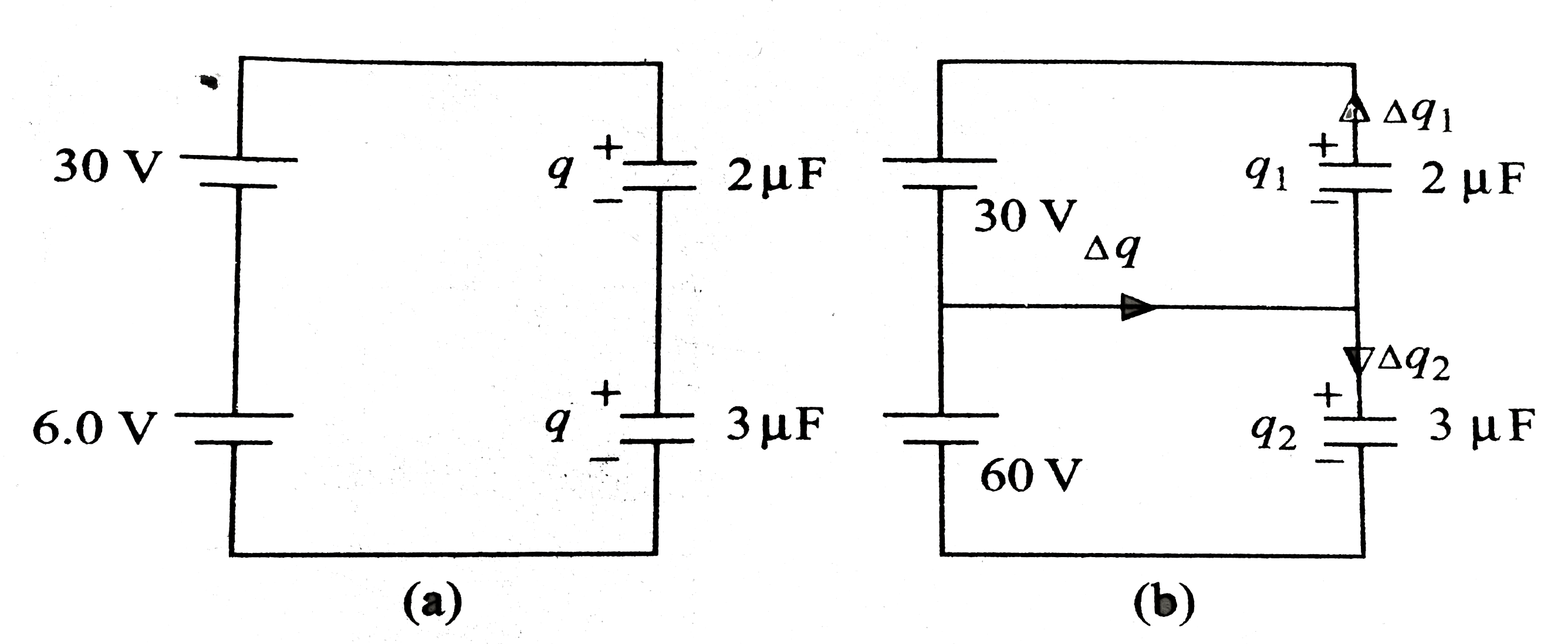
  1. In when the switch is swapped from 1 to 2, find the heat produced in t...

    Text Solution

    |

  2. A capacitor of capacitance C(1)=1 muF withstand a maximum voltage of V...

    Text Solution

    |

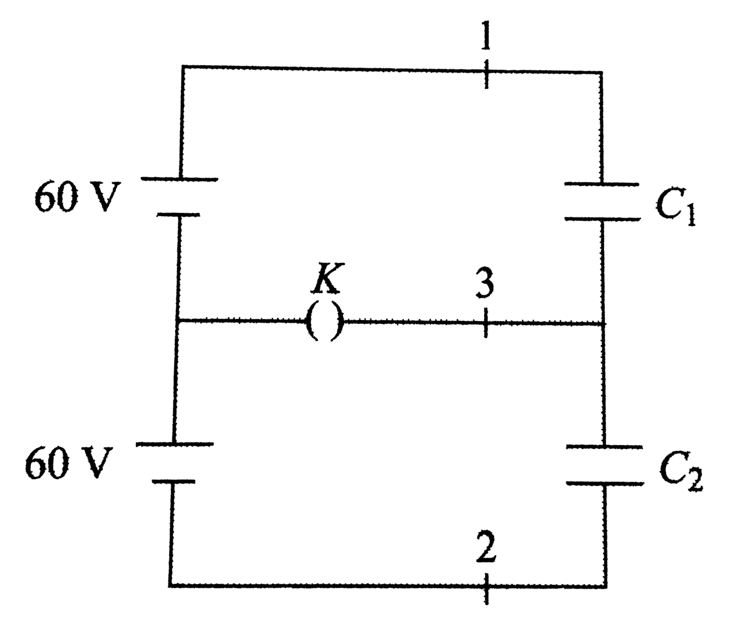
  3. In the circuit shown , the emf of each battery is 60 V and C(1)=2 muF ...

    Text Solution

    |

  4. A parallel plate capacitor contanins a mica sheet (thickness 0. 5+xx1...

    Text Solution

    |

  5. Find the potential difference between points M and N of the system sho...

    Text Solution

    |

  6. Several capacitors are connected as shown in. If the charge on the 5 m...

    Text Solution

    |

  7. Find the potential differnce between the points A and B and that betwe...

    Text Solution

    |

  8. Some capacitors each of capacitance 30 muF are connected as shown in. ...

    Text Solution

    |

  9. Two capacitors C(1) and C(2) are connected with two batteries of emf e...

    Text Solution

    |

  10. Find the potential difference between the points A and B in the circui...

    Text Solution

    |

  11. Shows a capacitive circuit, with a switch S(W). . a. What is the p...

    Text Solution

    |

  12. Shows an arrangement of identical metal plates paraed parallel to each...

    Text Solution

    |

  13. Two identical capacitors connected as shown and having initial charge ...

    Text Solution

    |

  14. Three capacitors each having capacitance C=2 muF are connected with a ...

    Text Solution

    |

  15. Five identical capacitors each of magnityde 5 muF are arranged with a ...

    Text Solution

    |

  16. When switch S is thrown to the left in figure, the plates of capacitor...

    Text Solution

    |

  17. A capacitor of capacitance C(0) is charged to a patential V(0) and the...

    Text Solution

    |

  18. Two dielectric slabs of relative oremittivities epsilon(r(1))=2 and ...

    Text Solution

    |

  19. Suppose n conducting face to face, and the distance between two succes...

    Text Solution

    |

  20. The arrangement of parallel conducting plates shown in are of the sam...

    Text Solution

    |