Home
Class 12
PHYSICS
shows two capacitors in series, the rigi...

shows two capacitors in series, the rigid central conducting section of length `b` being movable vertically.
.
If the potentials of the upper and lower plates are `V_(1)` and `V_(2)` respectively, then potebtial of rigid segid secton is.

A

`V_(1)-((V_(1)-V_(2))x)/((a-b))`

B

`V_(1)-((V_(2)-V_(1))x)/((a-b))`

C

`V_(1)-((V_(1)-V_(2))x)/((a+b))`

D

`V_(1)-((V_(1)-V_(2))x)/((a+b))`

Text Solution

Verified by Experts

The correct Answer is:
A

The circuit is equicalent to two capacitors in series.
.
`C_(1)=(epsilon_(0)A)/A`
`C_(2)=(epsilon_(0)A)/((a-b-x))`
`1/C_(eq)=1/(epsilon_(0)A)[a-b-x+x]=((a-b))/(epsilon_(0)A)`
We can reduce this structure in this srrucure in the following ciruit.
`(V_(1)-V)=(V_(1)-V_(2))C_(2)/(C_(1)+C_(2))`
.
`V_(1)-V=(V_(1)-V_(2))((epsilon_(0)A)/((a-b-x)))/((epsi_(0)A)/(x)+(epsi_(0)A)/(a-b-x))`
`=(V_(1)-V_(2))x/((a-b))-(V_(1)-V_(2))x/((a-b))`.
Promotional Banner

Topper's Solved these Questions

  • CAPACITOR AND CAPACITANCE

    CENGAGE PHYSICS ENGLISH|Exercise Integer|5 Videos
  • CAPACITOR AND CAPACITANCE

    CENGAGE PHYSICS ENGLISH|Exercise Multile Correct|11 Videos
  • ATOMIC PHYSICS

    CENGAGE PHYSICS ENGLISH|Exercise ddp.4.3|15 Videos
  • CENGAGE PHYSICS DPP

    CENGAGE PHYSICS ENGLISH|Exercise subjective type|51 Videos

Similar Questions

Explore conceptually related problems

Shows two capacitors in series, the rigid central conducting section of length b being movable vertically. . The equivalent capacitance of the given structure is .

Figure shows two capacitors in series. The rigid center section of length .b. is movable. The area of each plate is S. If the voltage difference between the plates is maintained constant at V_0 The change in stored energy if the center section is removed is

A circuit has a section ABC if the potential at point A,B and C are V_(1) , V_(2) and V_(3) respectively , calculate the potential at point O

Three capacitors C_(1),C_(2) and C_(3) are connected as shown in, The potentials of P,Q , and R are V_(1),V_(2), and V_(3) , respectively. Find the potential V_(0) at the function O . .

Two dielectric slabs of area of cross-section same as the area of the plates are introduced inside a capacitor as shown. Now, the capacitor is charged. If the potential of the upper plate of the capacitor is V_(H) and the potential of the lower plate is V_(L) , the potential at the interface of the two slabs is:

Three uncharged capacitors are connected as shown in the figure. If potentials at point P, Q and R are maintained at 1V, 2V, 3V respectively, then potential at O becomes .

Two capacitors C_1 and C_2 are charged to 120V and 200V respectively. It is found that connecting them together the potential on each one can be made zero. Then

A system of identical cylinders and plates is shown in Fig. All the cylinders are identical and there is no slipping at any contact. The velocity of lower and upper plates are V and 2V , respectively, as shown in Fig. Then the ratio of angular speeds of the upper cylinders to lower cylinders is

A system of identical cylinders and plates is shown in Fig. All the cylinders are identical and there is no slipping at any contact. The velocity of lower and upper plates are V and 2V , respectively, as shown in Fig. Then the ratio of angular speeds of the upper cylinders to lower cylinders is

A copper wire and an iron wire, each having an area of cross-section A and lengths L_(1) and L_(2) are joined end to end. The copper end is maintained at a potential V_(1) and the iron end at a lower potential V_(2) . If sigma_(1) and sigma_(2) are the conductivities of copper and iron respectively, then the potential of the junction will be

CENGAGE PHYSICS ENGLISH-CAPACITOR AND CAPACITANCE-Comprhension
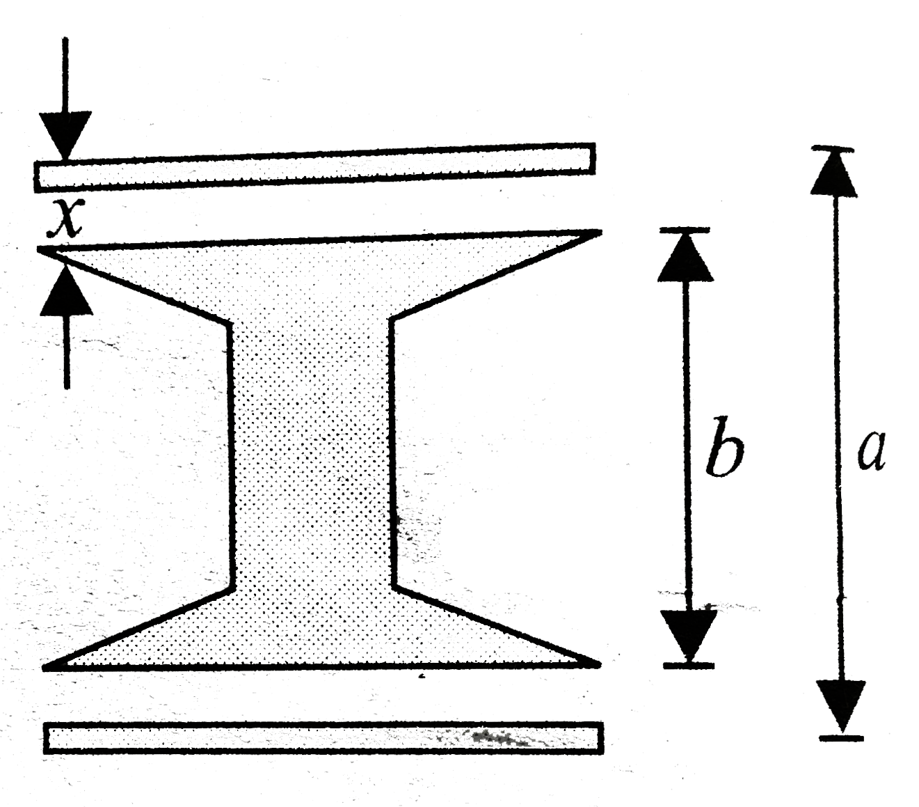
  1. Shows two capacitors in series, the rigid central conducting section o...

    Text Solution

    |

  2. shows two capacitors in series, the rigid central conducting section o...

    Text Solution

    |

  3. A 1muF capacitor and a 2µF capacitor are connected in series across a ...

    Text Solution

    |

  4. A 1muF capacitor and a 2µF capacitor are connected in series across a ...

    Text Solution

    |

  5. In the arrangement shown in in the switch S is , find the final c...

    Text Solution

    |

  6. In the arrangement shown in , the switch S is find the final poten...

    Text Solution

    |

  7. In the arrangement shown in, When the switch S is closed, find . ...

    Text Solution

    |

  8. Each plate of a parallel plate air capacitor has area S=5xx10^(-3) m^(...

    Text Solution

    |

  9. Each plate of a parallel plate air capacitor has area S=5xx10^(-3) m^(...

    Text Solution

    |

  10. Each capacitor has cpacitance C. . The equivalent capacitance betw...

    Text Solution

    |

  11. Each capacitor has cpacitance C. . The capacitance between 1 and 3...

    Text Solution

    |

  12. Consider . The charge appearing is C(2) is.

    Text Solution

    |

  13. Consider . The potential difference V(A)-V(B) is.

    Text Solution

    |

  14. Consider . The condition for which the potential difference betwee...

    Text Solution

    |

  15. In each capacitance C(1) is 6.0 muF, and each capacitance C(2) is 4.0 ...

    Text Solution

    |

  16. In each capacitance C(1) is 6.0 muF, and each capacitance C(2) is 4.0 ...

    Text Solution

    |

  17. In each capacitance C(1) is 6.0 muF, and each capacitance C(2) is 4.0 ...

    Text Solution

    |

  18. Condsider . In the circuit shown is the switch can be shifted to p...

    Text Solution

    |

  19. Condsider . Now the switch is shifted to position 2. The charge ap...

    Text Solution

    |

  20. Condsider . The charge on capacitor C(1) is.

    Text Solution

    |