Home
Class 12
PHYSICS
Condsider . Now the switch is shifte...

Condsider
.
Now the switch is shifted to position `2`. The charge appearing on capacitor `C_(3)` is`

A

`225 muC`

B

`235 muC`

C

`270 muC`

D

`75 muC`

Text Solution

Verified by Experts

The correct Answer is:
A

When switch is in position `1`,
`30=q/(20)-q/(30)=0` or `q=360 muC`
Now, the switch is in position`2`,
.
Loop` ABCD`,

`(Q'_(1))/(20)-(Q'_(1))/(30)+Q_(3)/(20)=0`
or `-3q'_(1)-2q_(1)+3q_(3)=0`
or `5q'_(1)=3q_(3)` or `q'_(1)=(3)/(5)q_(3)`
`(8q_(3))/5=360`
`q_(3)=(360xx5)/8=(450)/2muC=225muC` (ii)
`q'_(1)=3/5((450)/(2))=135 muC`.
Promotional Banner

Topper's Solved these Questions

  • CAPACITOR AND CAPACITANCE

    CENGAGE PHYSICS ENGLISH|Exercise Integer|5 Videos
  • CAPACITOR AND CAPACITANCE

    CENGAGE PHYSICS ENGLISH|Exercise Multile Correct|11 Videos
  • ATOMIC PHYSICS

    CENGAGE PHYSICS ENGLISH|Exercise ddp.4.3|15 Videos
  • CENGAGE PHYSICS DPP

    CENGAGE PHYSICS ENGLISH|Exercise subjective type|51 Videos

Similar Questions

Explore conceptually related problems

Condsider . The charge on capacitor C_(1) is.

Condsider . In the circuit shown is the switch can be shifted to positions 1 and 2 The charge on capacitor C_(1) when the switch is at position 1 is.

Consider . The charge appearing is C_(2) is.

In the circuit shown, the switch has been in position 1 for a long time. Now the switch is shifted to position 2. If this instant is taken as t = 0, then at time t=(pi)/(2)

V_C is the ideal voltmeter in the figure. Resistance of the resistor shown is R. Initially the switch is in position 2 when charging of the capacitor starts. Initially the capacitor was uncharged. The switch in circuit shifts automatically from 2 to 1 when V_C gt 2V//3 and goes back to 2 from 1 when V_C lt V//3 . The ideal voltmeter reads voltage across capacitor as plotted. What is the period T of the wave from in terms of R and C ? ,

Switch is in position A for long time. At time t = 0 it is shifted to position B. Find the maximum charge that will accumulate on capacitor

The capacitor C shown in the figure is in steady state condition when switch is shifted from position 1 to position 2.The heat liberated in the process is

Two identical capacitors are connected in the circuit shown. C_(2) is charged to 100 V and switch S is shifted from position 1 to position 2 . The negative terminal of C_(2) is connected with the positive terminal of C_(1) . Find the work done by the battery. If the polarity of C_(2) were reversed, what work would have been done by the battery ?

In the following circuit, the switch S is closed at t = 0. The charge on the capacitor C_(1) as a function of time will be given by (C_(eq)=(C_(1)C_(2))/(C_(1)+C_(2)))

In the circuit shown, switch S is placed in position 1 till the capacitor is charged to half of the maximum possible charge in this situation. Now, the switch S is placed in position 2. The maximum energy lost by the circuit after switch S is placed in position 2 is

CENGAGE PHYSICS ENGLISH-CAPACITOR AND CAPACITANCE-Comprhension
  1. In each capacitance C(1) is 6.0 muF, and each capacitance C(2) is 4.0 ...

    Text Solution

    |

  2. In each capacitance C(1) is 6.0 muF, and each capacitance C(2) is 4.0 ...

    Text Solution

    |

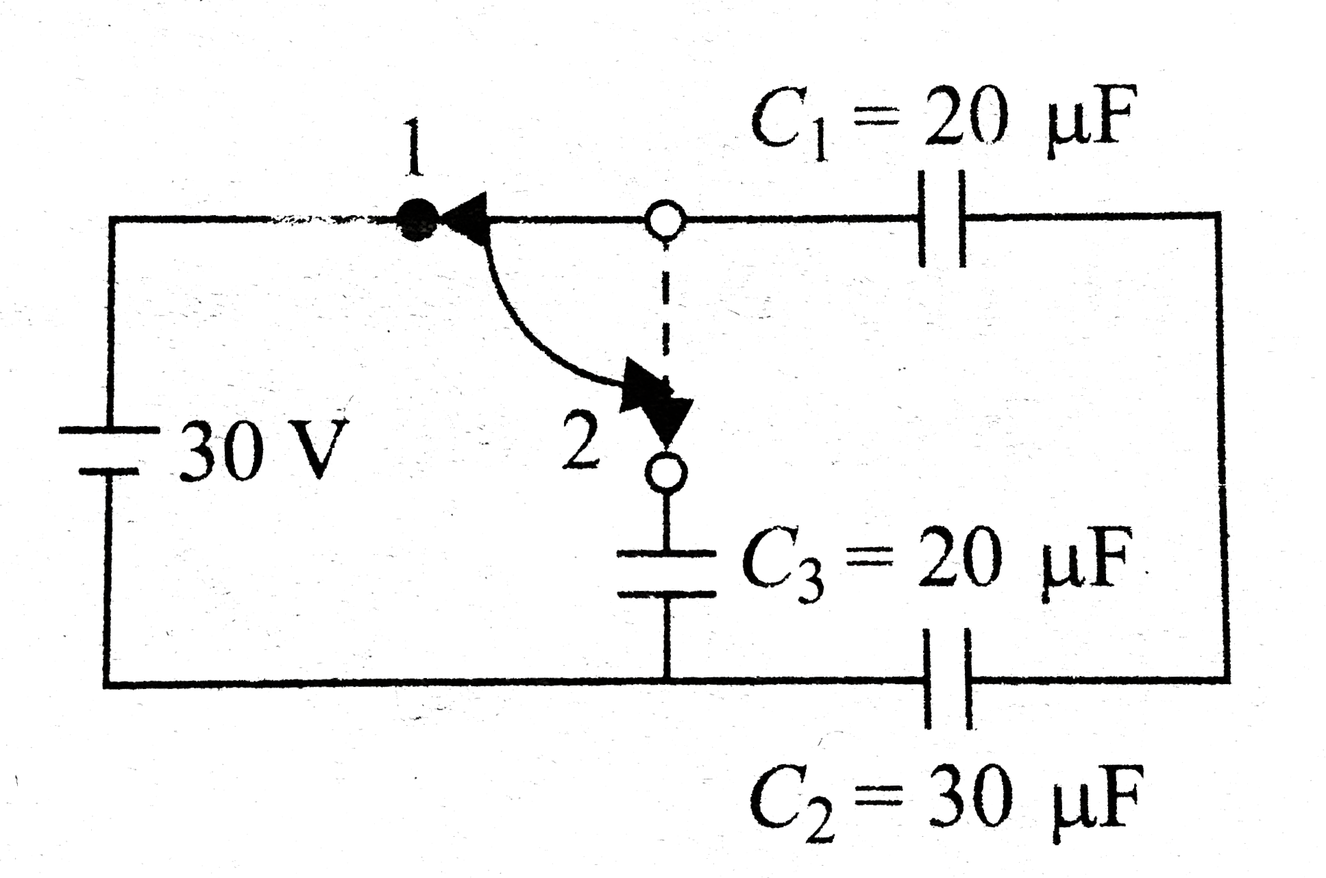
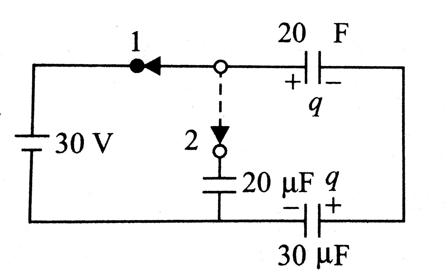
  3. Condsider . In the circuit shown is the switch can be shifted to p...

    Text Solution

    |

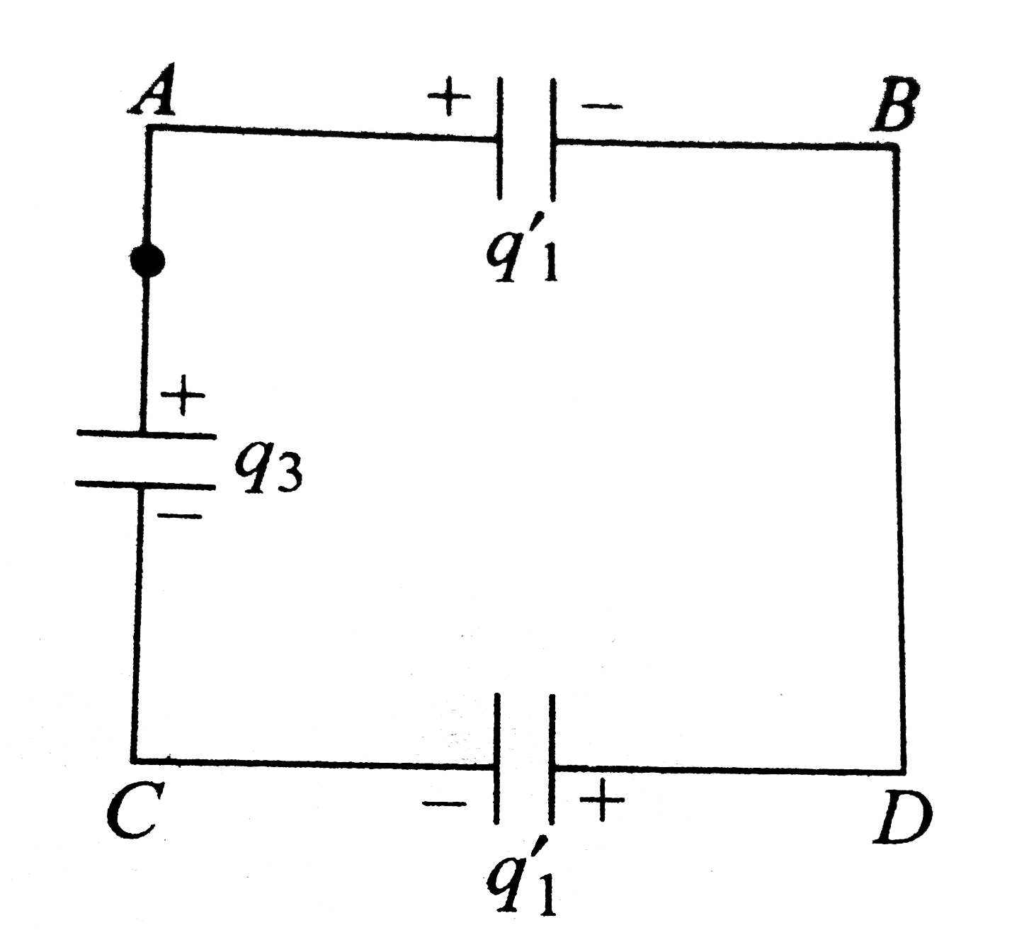
  4. Condsider . Now the switch is shifted to position 2. The charge ap...

    Text Solution

    |

  5. Condsider . The charge on capacitor C(1) is.

    Text Solution

    |

  6. For the system shown in capacitance is C The left plate is given a cha...

    Text Solution

    |

  7. For the system shown in capacitance is C The left plate is given a ch...

    Text Solution

    |

  8. Consider the circuit shown in figure, after switch S is closed. W...

    Text Solution

    |

  9. Consider the circuit shown in figure, after switch S is closed. W...

    Text Solution

    |

  10. Two capacitors of capacity 6 muF and 3 muF are charge 100 V and 50 V s...

    Text Solution

    |

  11. Two capacitors of capacity 6 muF and 3 muF are charge 100 V and 50 V s...

    Text Solution

    |

  12. Two capacitors of capacity 6 muF and 3 muF are charge 100 V and 50 V s...

    Text Solution

    |

  13. Two capacitors of capacity 6 muF and 3 muF are charge 100 V and 50 V s...

    Text Solution

    |

  14. The given circuit shows an arrangement of four capacitors. A potential...

    Text Solution

    |

  15. The given circuit shows an arrangement of four capacitors. A potential...

    Text Solution

    |

  16. The given circuit shows an arrangement of four capacitors. A potential...

    Text Solution

    |

  17. Let us now connect two more capacitors in the circuit. One of them, C(...

    Text Solution

    |

  18. Let us now connect two more capacitors in the circuit. One of them, C(...

    Text Solution

    |

  19. Shows a diagonal symmetric arrangement of capacitors and a battery. ...

    Text Solution

    |

  20. Shows a diagonal symmetric arrangement of capacitors and a battery. ...

    Text Solution

    |