Home
Class 12
PHYSICS
Three ammeters A,B, and C of resistances...

Three ammeters `A,B`, and `C` of resistances `R_A,R_b` and `R_C` respectively are joined as shown. When some potential difference is appllied across the terminals `T_1` and `T_2` their readings are `I_A,I_B and I_C` respectively Then,

A

`I_(A) = I_(B)`

B

`I_(A)R_(A)+ I_(B)R_(B)= I_(C)R_(C)`

C

`I_(A)/I_(C) = R_(C)/R_(A)`

D

`I_(B)/I_(C) = R_C/(R_A+R_B)`

Text Solution

Verified by Experts

The correct Answer is:
A, B, D

a., b., d.
As A and B are connected in series, hence IA = IB. The potential
difference acorss both the branches will be the same.

`I_(A)R_(B) + I_(B)R_(B) = I_(C)R_(C) or I_(B)/I_(C) = (R_C)/(R_A + R_B)` .
Promotional Banner

Topper's Solved these Questions

  • MISCELLANEOUS VOLUME 3

    CENGAGE PHYSICS ENGLISH|Exercise Assertion and Reason|8 Videos
  • MISCELLANEOUS VOLUME 3

    CENGAGE PHYSICS ENGLISH|Exercise Integer Answer Type|11 Videos
  • MISCELLANEOUS VOLUME 3

    CENGAGE PHYSICS ENGLISH|Exercise Assertion-Reasoning Type|1 Videos
  • MAGNETIC FIELD AND MAGNETIC FORCES

    CENGAGE PHYSICS ENGLISH|Exercise Multiple Correct Answer type|2 Videos
  • MISCELLANEOUS VOLUME 5

    CENGAGE PHYSICS ENGLISH|Exercise Integer|12 Videos

Similar Questions

Explore conceptually related problems

Three ammeters 1, 2, and 3 of resistances R_(1). R_(2) and R_(3) respectively are joined as shown. When some potential difference is applied across the terminals P and Q, their readings are I_(1), I_(2) and I_(3) , respectively. Then

Three voltmeters A, B and C having resistances R, 1.5 R and 3 R respectively are used in a circuit as shown. When a potential difference is applied between X and Y, the readings of the voltmeters are V_1, V_2 and V_3 respectively. Then :

A, B and C are voltmeters of resistances R, 1.5R and 3R respectively. When some potential difference is applied between x and y the voltmeter readings are V_A, V _B and V_C, then

A, B and C are voltmeters of resistances R, 1.5R and 3R respectively. When some potential difference is applied between x and y the voltmeter readings are V_A, V _B and V_C, then

A, B and C are voltmeters of resistances R, 1.5R and 3R respectively. When some potential difference is applied between x and y the voltmeter readings are V_A, V _B and V_C, then

A, B and C are voltmeters of resistances R, 1.5R and 3R respectively. When some potential difference is applied between x and y the voltmeter readings are V_A, V_B and V_C, then

In the circuit shown in fig. some potential difference is applied between A and B. The equivalent resistance between A and B is R.

In the circuit shown some potential difference is applied between A and B. The equivalent resistance between A and B is R. Then

In the given circuit, if I_1 and I_2 be the current in resistances R_1 and R_2 , respectively, then .

In the series L-C-R circuit , the voltmeter and ammeter readings are respectively

CENGAGE PHYSICS ENGLISH-MISCELLANEOUS VOLUME 3-Multiple correct Answer type
  1. In the circuit shows in Fig. 6.63, the cell is ideal with emf 9 V. If ...

    Text Solution

    |

  2. Which of the following statements are correct?

    Text Solution

    |

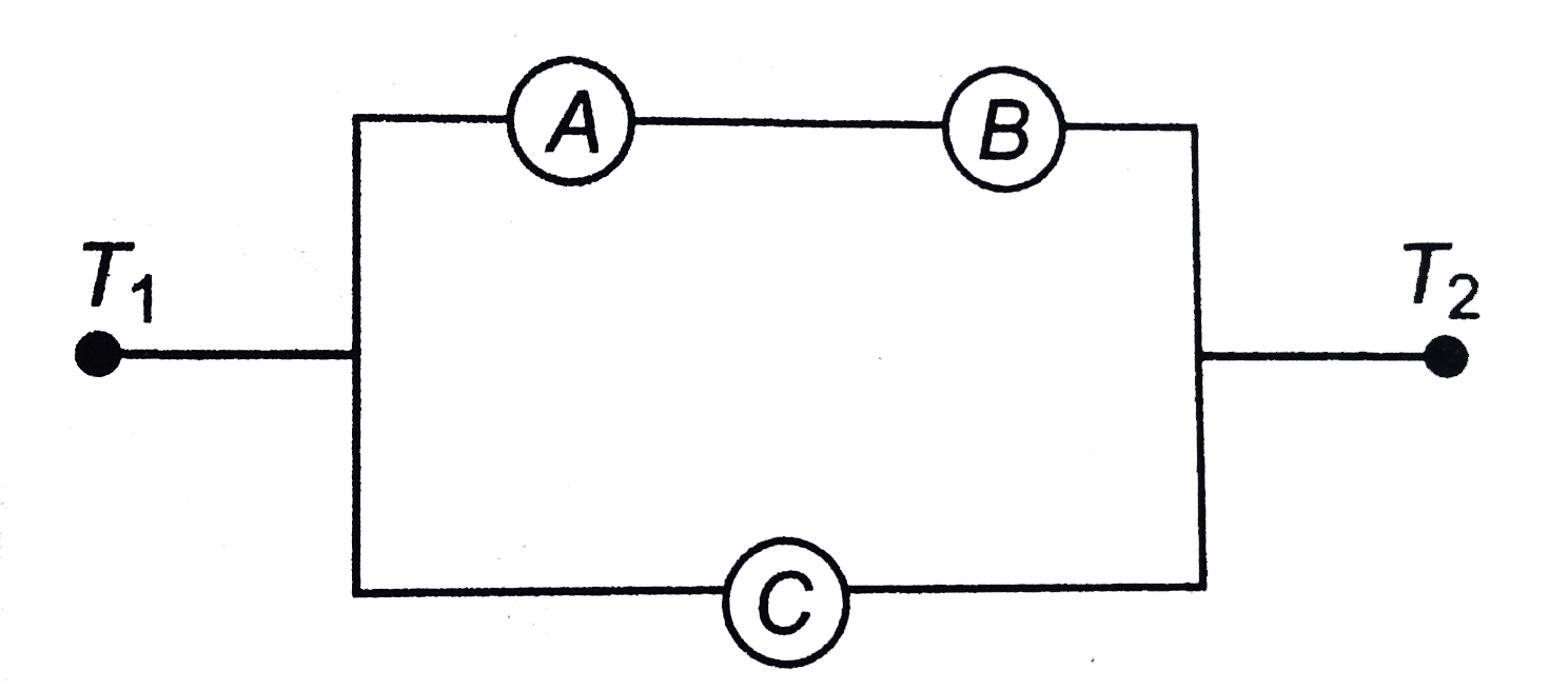
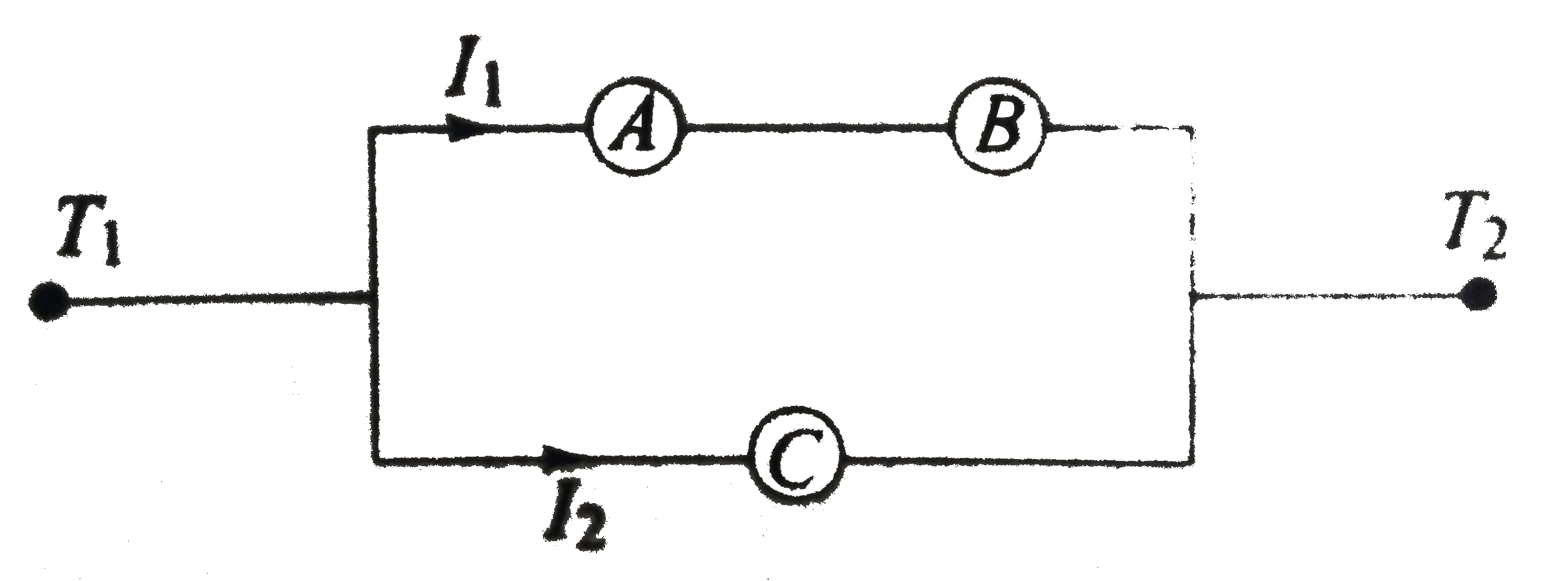
  3. Three ammeters A,B, and C of resistances RA,Rb and RC respectively are...

    Text Solution

    |

  4. A battery of emf 2 V and initial resistance 1 Omega is connected acr...

    Text Solution

    |

  5. Two electric bulbs , rated at (25W,220V) and (100W,220V), are conne...

    Text Solution

    |

  6. In the circuit shown in figure

    Text Solution

    |

  7. A battery of emf epsilon0 = 5V and internal resistance 5 Omega is conn...

    Text Solution

    |

  8. The diagram shows a modified meter bridge, which is used for measuring...

    Text Solution

    |

  9. A parallel plate capacitor of capacitance 10muF is connected to a cell...

    Text Solution

    |

  10. The galvanometer shown in the figure has resistance 10Omega. It is shu...

    Text Solution

    |

  11. In the circuit shown in figure, E1 and E2 are tow ideal sources of unk...

    Text Solution

    |

  12. Consider a resistor of uniform cross-sectional area connected to a bat...

    Text Solution

    |

  13. A variable current flows through a 1Omega resistor for 2 s. Time depe...

    Text Solution

    |

  14. In the circuit shown in the figure .

    Text Solution

    |

  15. Two light bulbs shown in the circuit have rating A(24 V, 24W) and B(24...

    Text Solution

    |

  16. If the switch at point P is opened (shown in the figure), choose the c...

    Text Solution

    |

  17. Current through the battery in the circuit shown in the figure

    Text Solution

    |

  18. In the circuit shown in figure,

    Text Solution

    |

  19. In the given circuit, the value of m is varying. The correct statement...

    Text Solution

    |

  20. A circuit is shown below.

    Text Solution

    |