A
B
C
D
Text Solution
Verified by Experts
The correct Answer is:
 .
. 


Topper's Solved these Questions
MISCELLANEOUS VOLUME 3
CENGAGE PHYSICS ENGLISH|Exercise Assertion and Reason|8 VideosMISCELLANEOUS VOLUME 3
CENGAGE PHYSICS ENGLISH|Exercise Integer Answer Type|11 VideosMISCELLANEOUS VOLUME 3
CENGAGE PHYSICS ENGLISH|Exercise Assertion-Reasoning Type|1 VideosMAGNETIC FIELD AND MAGNETIC FORCES
CENGAGE PHYSICS ENGLISH|Exercise Multiple Correct Answer type|2 VideosMISCELLANEOUS VOLUME 5
CENGAGE PHYSICS ENGLISH|Exercise Integer|12 Videos
Similar Questions
Explore conceptually related problems
CENGAGE PHYSICS ENGLISH-MISCELLANEOUS VOLUME 3-Multiple correct Answer type
- A parallel plate capacitor of capacitance 10muF is connected to a cell...
Text Solution
|
- The galvanometer shown in the figure has resistance 10Omega. It is shu...
Text Solution
|
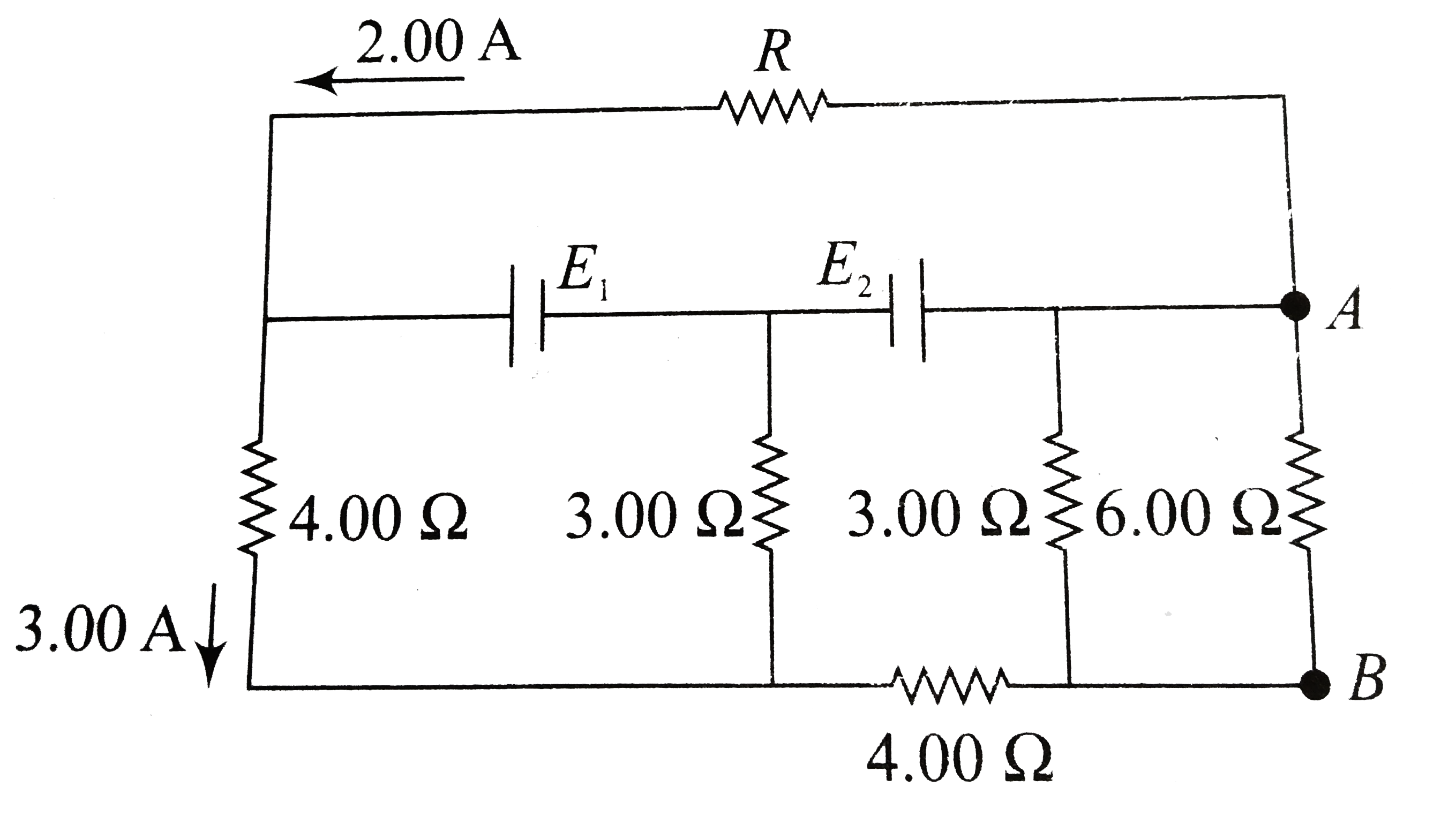
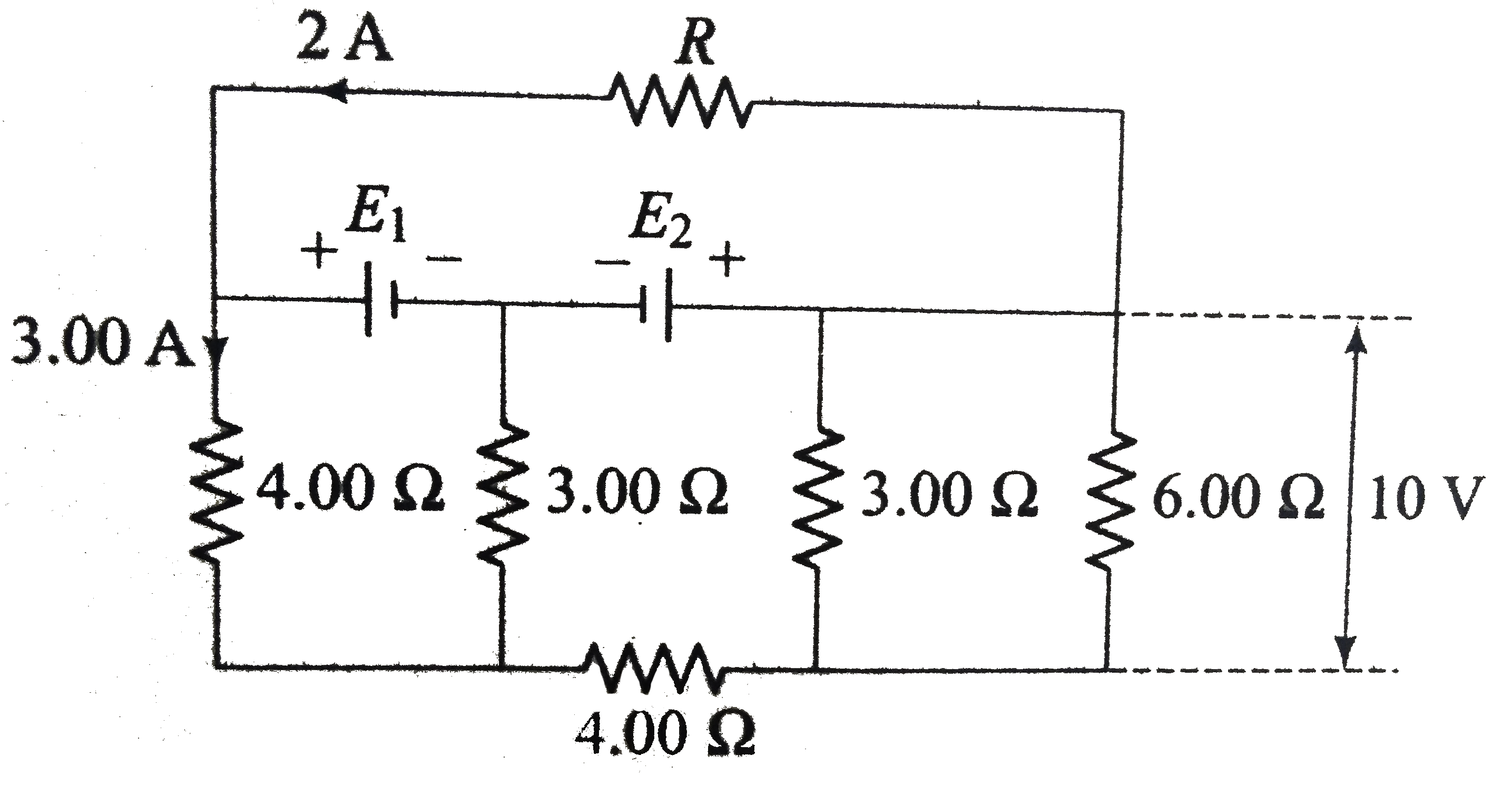
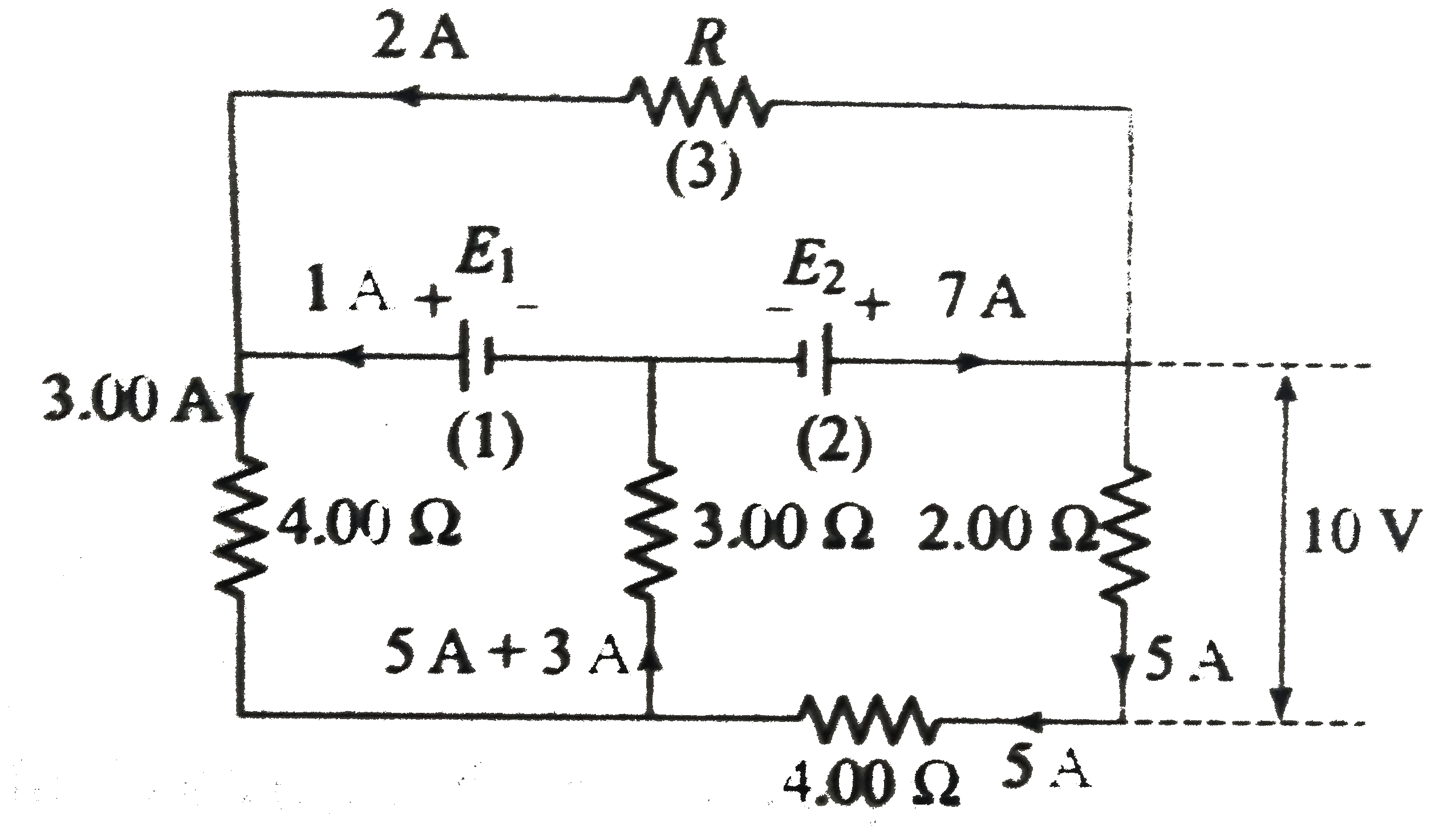
- In the circuit shown in figure, E1 and E2 are tow ideal sources of unk...
Text Solution
|
- Consider a resistor of uniform cross-sectional area connected to a bat...
Text Solution
|
- A variable current flows through a 1Omega resistor for 2 s. Time depe...
Text Solution
|
- In the circuit shown in the figure .
Text Solution
|
- Two light bulbs shown in the circuit have rating A(24 V, 24W) and B(24...
Text Solution
|
- If the switch at point P is opened (shown in the figure), choose the c...
Text Solution
|
- Current through the battery in the circuit shown in the figure
Text Solution
|
- In the circuit shown in figure,
Text Solution
|
- In the given circuit, the value of m is varying. The correct statement...
Text Solution
|
- A circuit is shown below.
Text Solution
|
- In the given circuit, mark the correct statement// statements.
Text Solution
|
- In the circuit, various resistance and five batteries are connected as...
Text Solution
|
- In the circuit shown in figure, E1 and E2 are two ideal sources of unk...
Text Solution
|
- Inside a supeerconducting ring, six identical resistors each of resist...
Text Solution
|
- In question 28, the equivalent resistances
Text Solution
|
- Imagine a light planet revolving around a very massive star in a circu...
Text Solution
|
- A series circuit consists of two capacitors, a resistors, and an ideal...
Text Solution
|
- A circuit contains an ideal battery , three resistors, and tow ideal a...
Text Solution
|