A
B
C
D
Text Solution
Verified by Experts
The correct Answer is:


Topper's Solved these Questions
MISCELLANEOUS VOLUME 3
CENGAGE PHYSICS ENGLISH|Exercise Assertion and Reason|8 VideosMISCELLANEOUS VOLUME 3
CENGAGE PHYSICS ENGLISH|Exercise Integer Answer Type|11 VideosMISCELLANEOUS VOLUME 3
CENGAGE PHYSICS ENGLISH|Exercise Assertion-Reasoning Type|1 VideosMAGNETIC FIELD AND MAGNETIC FORCES
CENGAGE PHYSICS ENGLISH|Exercise Multiple Correct Answer type|2 VideosMISCELLANEOUS VOLUME 5
CENGAGE PHYSICS ENGLISH|Exercise Integer|12 Videos
Similar Questions
Explore conceptually related problems
CENGAGE PHYSICS ENGLISH-MISCELLANEOUS VOLUME 3-Multiple correct Answer type
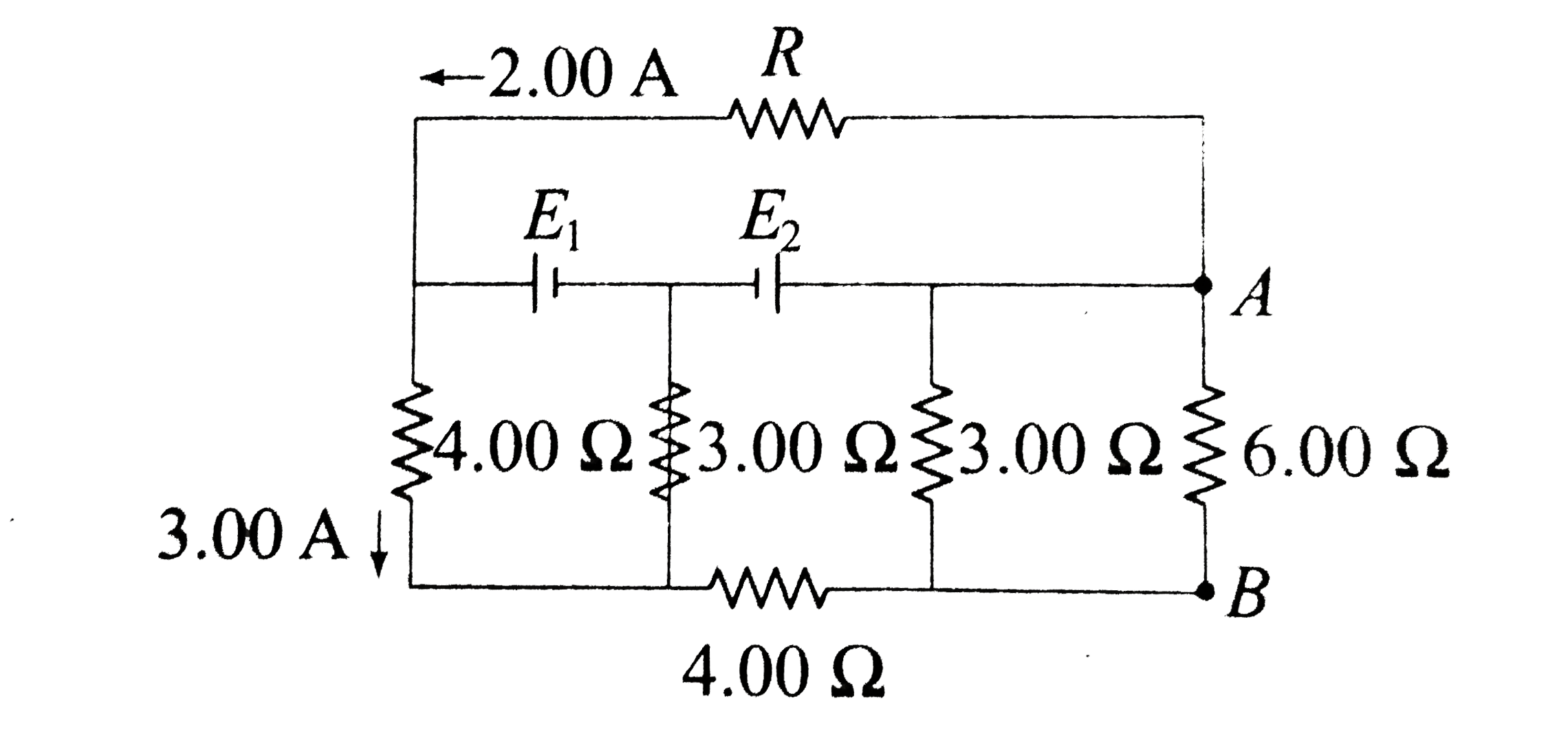
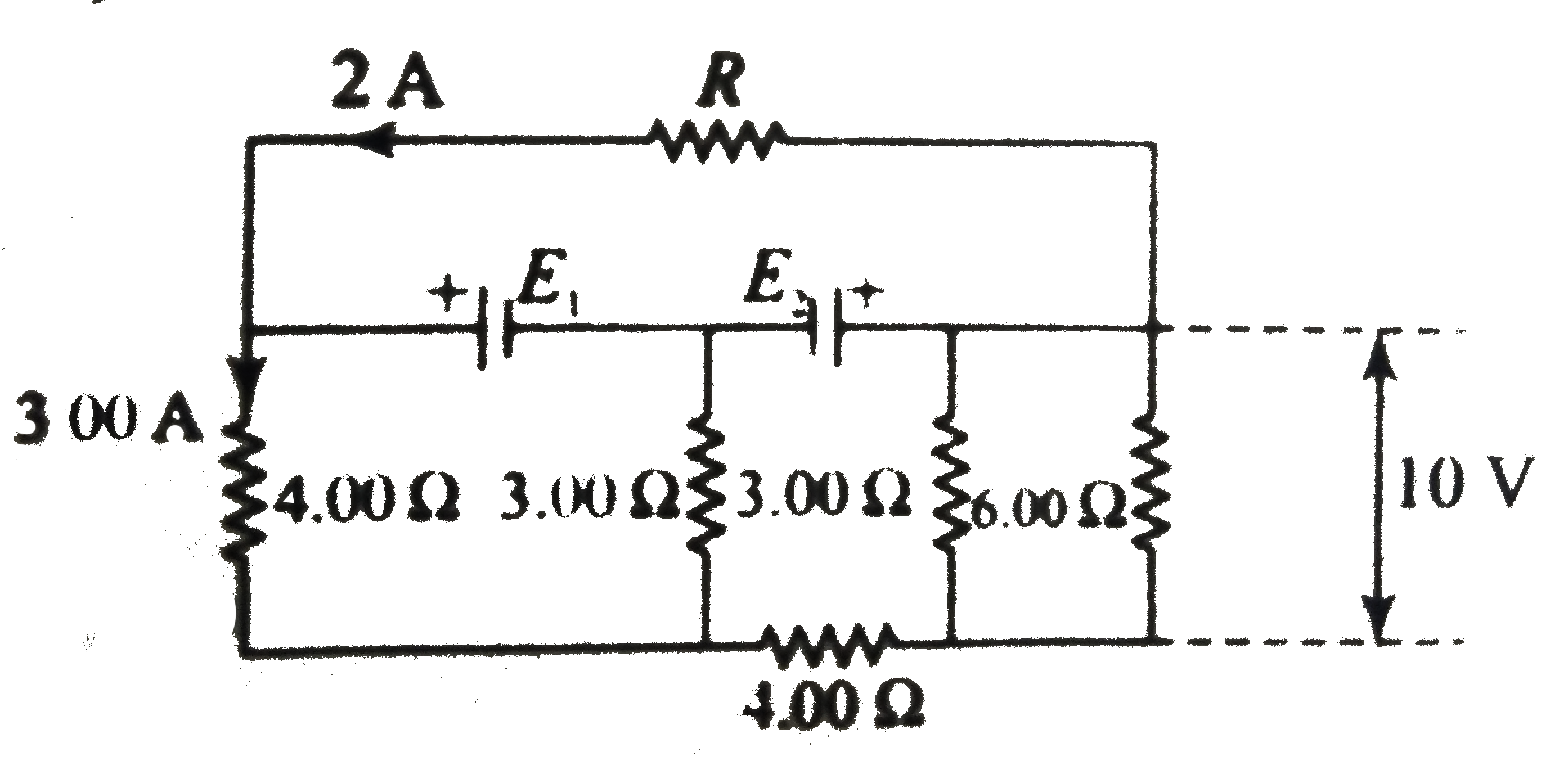
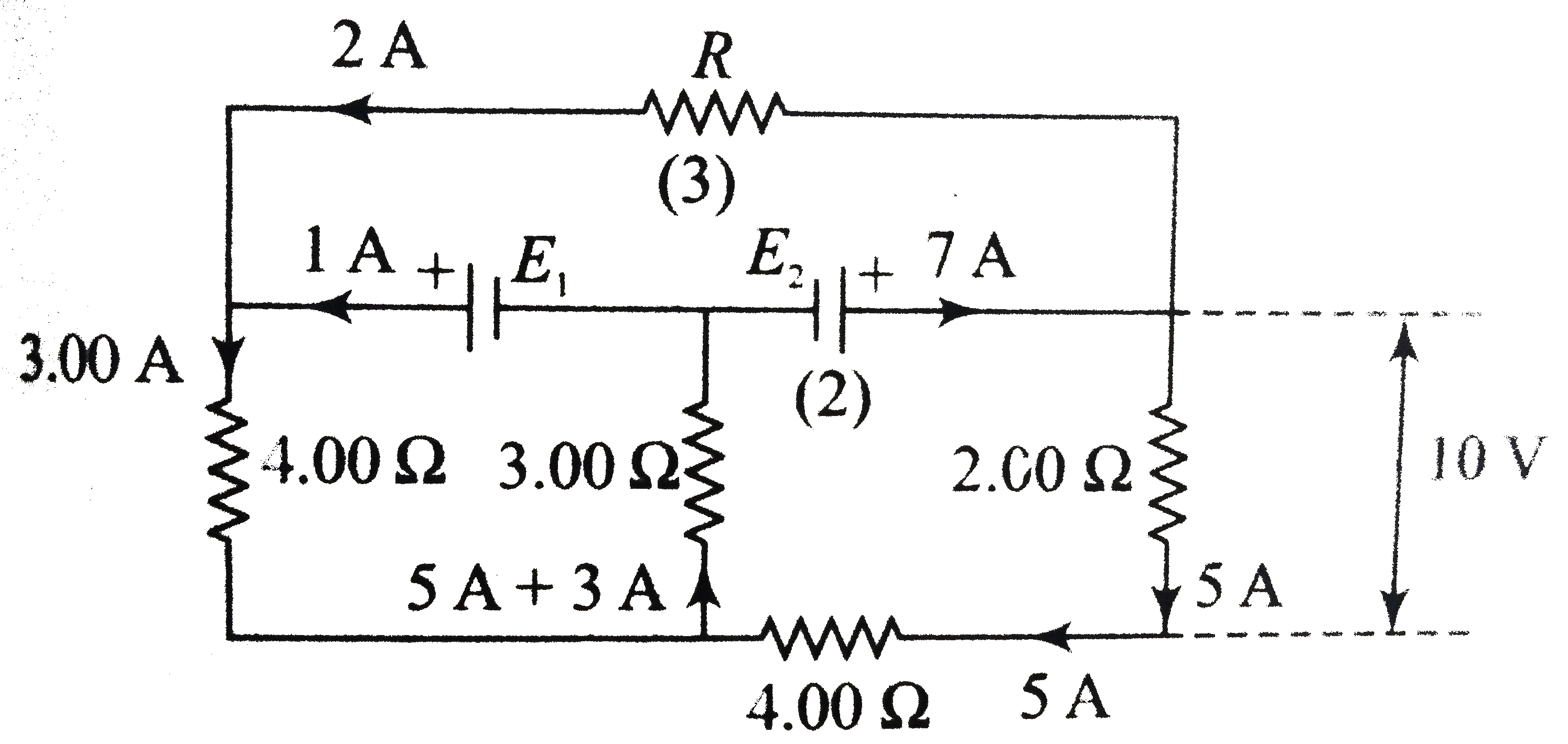
- A circuit is shown below.
Text Solution
|
- In the given circuit, mark the correct statement// statements.
Text Solution
|
- In the circuit, various resistance and five batteries are connected as...
Text Solution
|
- In the circuit shown in figure, E1 and E2 are two ideal sources of unk...
Text Solution
|
- Inside a supeerconducting ring, six identical resistors each of resist...
Text Solution
|
- In question 28, the equivalent resistances
Text Solution
|
- Imagine a light planet revolving around a very massive star in a circu...
Text Solution
|
- A series circuit consists of two capacitors, a resistors, and an ideal...
Text Solution
|
- A circuit contains an ideal battery , three resistors, and tow ideal a...
Text Solution
|
- AB is part of a circuit as shown that absorbs energy at a rate of 50W....
Text Solution
|
- The switch S has been closed for long time and the electric circuit sh...
Text Solution
|
- In the circuit shown, the resistances are given in ohms and the batter...
Text Solution
|
- In the circuit shown, battery, ammeter , and voltmeter are ideal and t...
Text Solution
|
- All the resistance in the given Wheatstone bridge have different value...
Text Solution
|
- Capacitor C(1) of capacitance 1 muF and capacitor C(2) of capacitance ...
Text Solution
|
- Read the following statements carefully Y: The resistivity of semico...
Text Solution
|
- In the circuit shown in figure the current through
Text Solution
|
- When a potential difference is applied across, the current passing thr...
Text Solution
|
- For the circuit shown in figure
Text Solution
|
- For the resistance network shown in the figure, choose the correct opt...
Text Solution
|