Home
Class 12
PHYSICS
In the circuit shows in Fig. , E = 10 V,...

In the circuit shows in Fig. , `E = 10 V`, `R_(1) = 5 Omega`, `R_(2) = 10 Omega`, and `L = 5 H`. For the two separate conditions, (i) switch `S` is just closed and (ii) switch `S` is closed for a long time, calculate
a. current `i_(1)` through `R_(1)`,
b. current `i_(2)` through `R_(2)`,
c. current `i` through the switchs,
d. the potential difference across `R_(2)`,
e. the potential difference across `L`,
f. `di_(2)//dt`.

Text Solution

Verified by Experts

(I) At `t = 0`, inductor acts as open circuit:

a. `i_(l) = (E)/(R_(1)) = 2A` b. `i_(2) = 0A`
c. `i = i_(1) + i_(2) + 0 = 2 A` d. `V` across resistor `R_(2) = 0`
e. `V` across `L = 10 V`
f. `L(di_(2))/(dt) = 10 rArr (di_(2))/(dt) = (10)/(5) = 2 A//s`
(II) At `t = oo`, inductor acts as a conducing wire:

a. `i_(1) = (E)/(R_(1)) = 2 A`
b. `i_(2) = (E)/(R_(2)) = (10)/(10) = 1 A`
c. `i_("switch") = i_(1) + i_(2) = 3 a`
d. `V_(R2) = 10 V`
e. `V_(L) 0 V`
f. Current in `R_(2)` is not changing with time, so
`(di_(2))/(dt) = 0`
Promotional Banner

Topper's Solved these Questions

  • INDUCTANCE

    CENGAGE PHYSICS ENGLISH|Exercise Exercises (subjective)|7 Videos
  • INDUCTANCE

    CENGAGE PHYSICS ENGLISH|Exercise Exercises (single Correct )|65 Videos
  • INDUCTANCE

    CENGAGE PHYSICS ENGLISH|Exercise Solved Examples|3 Videos
  • HEATING EFFECT OF CURRENT

    CENGAGE PHYSICS ENGLISH|Exercise Thermal Power in Resistance Connected in Circuit|27 Videos
  • MAGNETIC FIELD AND MAGNETIC FORCES

    CENGAGE PHYSICS ENGLISH|Exercise Multiple Correct Answer type|2 Videos

Similar Questions

Explore conceptually related problems

In the circuit shown below E_(1) = 4.0 V, R_(1) = 2 Omega, E_(2) = 6.0 V, R_(2) = 4 Omega and R_(3) = 2 Omega . The current I_(1) is

A cell supplies a current i_(1) trhough a resistnace R_(1) and a current i_(2) through a resistance R_(2) . The internal resistance of this cell is

In the circuit shown in fig. R_(1) = 10 Omega, R_(2) = 5 Omega, C_(1) = 1 muF, C_(2) = 2muF, and E =6V. Calculate the charge on each capactor in the stedy state.

In the circuit diagram shown in Figure E=18V , L=2H, R_(1)=3Omega , R_(2)=6Omega . Switch S is closed at t=0 Match the following:

In the following circuit , E_1 = 4V, R_1 = 2 Omega, E_2 = 6 V, R_2 = 2Omega, and R_3 = 4Omega. Find the currents i_1 and i_2

In the given circuit, calculate - (a) the total resistance of the circuit, (b) the current through the circuit, and (c) the potential differences across R_(1) and R_(2)

In the circuit shown, E_(1)= 7 V, E_(2) = 7 V, R_(1) = R_(2) = 1Omega and R_(3) = 3 Omega respectively. The current through the resistance R_(3)

In the circuit shown, E_(1)= 7 V, E_(2) = 7 V, R_(1) = R_(2) = 1Omega and R_(3) = 3 Omega respectively. The current through the resistance R_(3)

As the switch S is closed in the circuit shown in figure, current passed through it is.

In the circuit shows in Fig E = 15 V , R_(1) = 1Omega , R_(2) = 1 Omega , R_(3) = 2Omega , and L = 1.5 H . The currents flowing through R_(1),R_(2) ,and R_(3) are i_(1),i_(2) , and i_(3) , respectively. Immediately after tuning switch S on,

CENGAGE PHYSICS ENGLISH-INDUCTANCE-Exercise 4.1
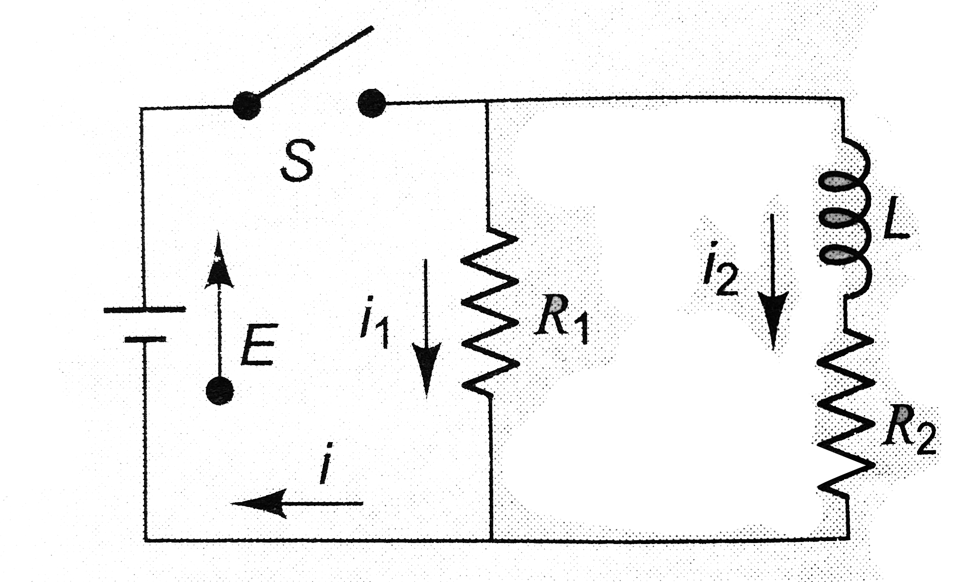
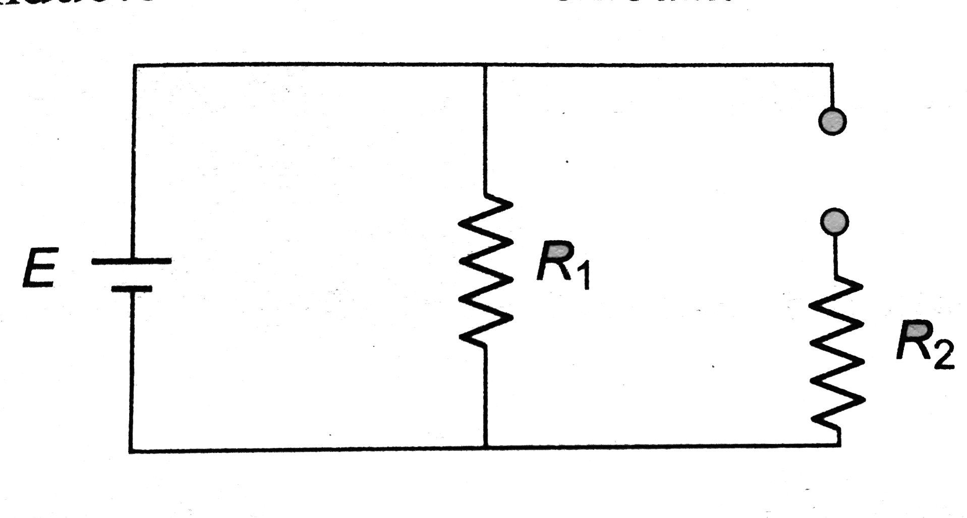
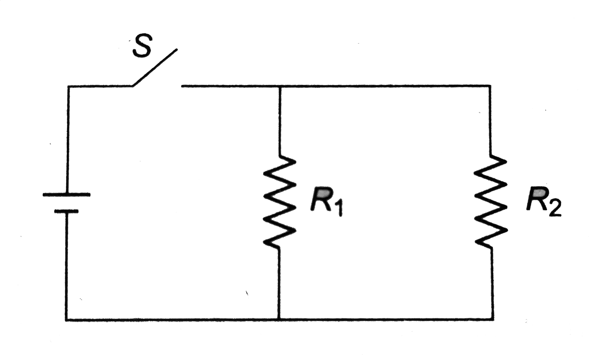
  1. Figure shows an LCR circuit. When the switch is closed, the currents t...

    Text Solution

    |

  2. It has been proposed to use large inductors as energy storage devices....

    Text Solution

    |

  3. A 1 -k Omega resistor is connected in series with a 10-mH inductor, a ...

    Text Solution

    |

  4. A capacitor with capacitance 6 xx 10^(-5) F is charged by connecting i...

    Text Solution

    |

  5. In the circuit shows in Fig. , E = 10 V, R(1) = 5 Omega, R(2) = 10 Ome...

    Text Solution

    |

  6. In Fig. the switch is closed and steady-state conditions are establish...

    Text Solution

    |

  7. The switch in figure is closed at time t = 0. Find the current in the ...

    Text Solution

    |

  8. AB is a part of circuit. Find the potential difference V(A) - V(B) if ...

    Text Solution

    |

  9. A circuit contains an ideal cell and an inductor with a switch. Initia...

    Text Solution

    |

  10. In the following circuit (Fig.) the switch is closed at t = 0. Find th...

    Text Solution

    |

  11. In a circuit S(1) remains closed for a long time and S(2) remain open....

    Text Solution

    |

  12. At t = 0, switch S is closed (shown in Fig.). After a long time, sudde...

    Text Solution

    |

  13. Which of the two curves shows has lesser time constant.

    Text Solution

    |

  14. Two insulated wires are wound on the same hollow cylinder, s as to fro...

    Text Solution

    |

  15. Find the mutual inductance of two concentric coils of radii a(1) and a...

    Text Solution

    |

  16. Solve problem 19 if the planes of the coils are perpendicular.

    Text Solution

    |

  17. Find the mutual inductance of two concentric coils of radii a(1) and a...

    Text Solution

    |

  18. Figure. shows two concentric coplanar coils with radii a and b(alt lt...

    Text Solution

    |

  19. Figure. shows two concentric coplanar coils with radii a and b(alt lt...

    Text Solution

    |

  20. If the current in the inner loop changes according to I = 2t^(2) (Fig ...

    Text Solution

    |