Text Solution
Verified by Experts


Topper's Solved these Questions
CURRENT ELECTRICITY
AAKASH INSTITUTE ENGLISH|Exercise ASSIGNMENT(SECTION-A(OBJECTIVE TYPE QUESTIONS))|69 VideosCURRENT ELECTRICITY
AAKASH INSTITUTE ENGLISH|Exercise ASSIGNMENT SECTION-B(OBJECTIVE TYPE QUESTION ))|44 VideosCURRENT ELECTRICITY
AAKASH INSTITUTE ENGLISH|Exercise ASSIGNMENT SECTION-J|10 VideosCOMMUNICATION SYSTEMS
AAKASH INSTITUTE ENGLISH|Exercise ASSIGNMENT SECTION D (Assertion-Reason)|10 VideosDUAL NATURE OF RADIATION AND MATTER
AAKASH INSTITUTE ENGLISH|Exercise ASSIGNMENT (SECTION-D)|10 Videos
Similar Questions
Explore conceptually related problems
AAKASH INSTITUTE ENGLISH-CURRENT ELECTRICITY-Try Yourself
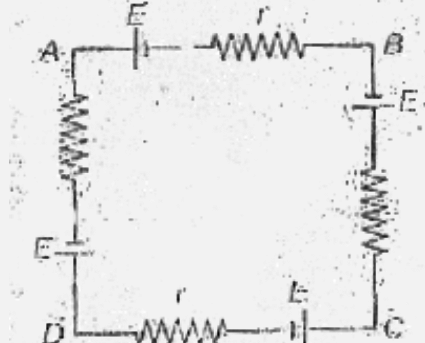
- Potential difference across AB in the network shown in figure.
Text Solution
|
- Maximum current produced by a cell of emf 10 V and internal resistan...
Text Solution
|
- When the positive and negative electrodes of a cell are denoted as P ...
Text Solution
|
- About internal resistance of a cell , the correct statements that it i...
Text Solution
|
- Find the current through the 10 Omega resistance connected across AB
Text Solution
|
- Four identical cells each having emf E and internal resistance r are c...
Text Solution
|
- The current l through the cell in the network shown is
Text Solution
|
- In the network shown below , potential difference across CD is
Text Solution
|
- The current l in the circuit shown below is
Text Solution
|
- Twelve identical resistance R each form a cube as shown in figure. Re...
Text Solution
|
- In the network shown , find the resistance across AB.
Text Solution
|
- In the metre bridge, the balancing length AB =l=20 cm. The unknown res...
Text Solution
|
- An unknown resistance R(1) is connected is series with a resistance of...
Text Solution
|
- Two cells of emf E(1) and E(2) are to be compared in a potentiometer...
Text Solution
|
- A simple potentiometer circuit is shown in figure. The internal resi...
Text Solution
|
- Consider the circuit shown in Figure . Ther terminal voltage of the 2...
Text Solution
|
- N sources of current with different emf's are connected as shown in Fi...
Text Solution
|
- Voltmeter V and Ammeter A are used to measure the total potential dif...
Text Solution
|
- Could the equation for R(3) lead to a negative valuefor this resistanc...
Text Solution
|
- Which of the two capacitor plates is at the higher potential ?
Text Solution
|