Text Solution
Verified by Experts


Topper's Solved these Questions
SEMICONDUCTOR ELECTRONICS (MATERIAL, DEVICES AND SIMPLE CIRUITS )
AAKASH INSTITUTE ENGLISH|Exercise TRY YOUR SELF|27 VideosSEMICONDUCTOR ELECTRONICS (MATERIAL, DEVICES AND SIMPLE CIRUITS )
AAKASH INSTITUTE ENGLISH|Exercise EXERCISE|20 VideosRAY OPTICS AND OPTICAL INSTRUMENTS
AAKASH INSTITUTE ENGLISH|Exercise ASSIGNMENT (SECTION - D)|16 VideosSEMICONDUCTOR ELECTRONICS: MATERIALS, DEVICES AND SIMPLE CIRCUITS
AAKASH INSTITUTE ENGLISH|Exercise Assignment (Section-D (Assertion and reason))|5 Videos
Similar Questions
Explore conceptually related problems
AAKASH INSTITUTE ENGLISH-SEMICONDUCTOR ELECTRONICS (MATERIAL, DEVICES AND SIMPLE CIRUITS )-Assignment SECTION - D (Assertion & reason type Question)
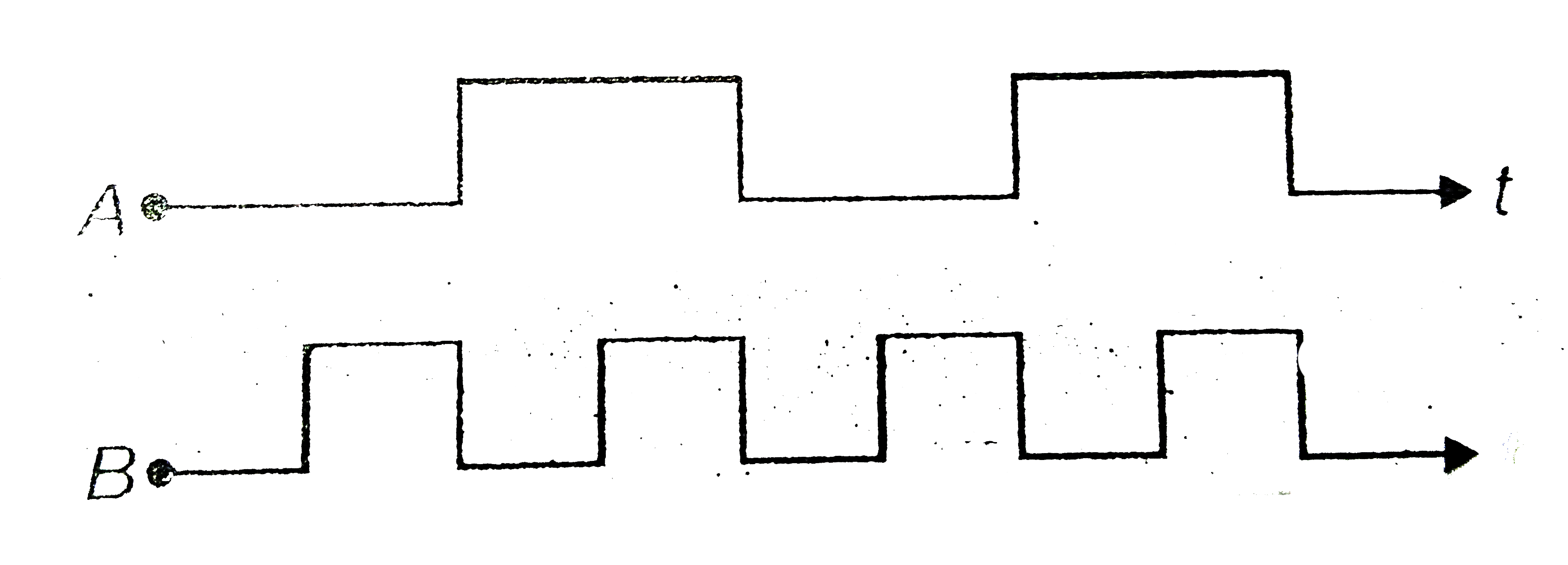
- Sketch the output waveform Y from a NAND gate having following inputs ...
Text Solution
|
- Intrinsic semiconductor at absolute zero temperature is a
Text Solution
|
- Assertion: When base region has large width, the collector current inc...
Text Solution
|
- A: The conductivity of a pure semiconductor increases on doping R: D...
Text Solution
|
- Assertion: Semiconductor do not obey Ohm's law. Reason: Current is d...
Text Solution
|
- A: When a pure semiconductor is doped with a pentavalent impurity, the...
Text Solution
|
- Assertion : In transistor common emitter mode as an amplifier is pref...
Text Solution
|
- Assertion : The energy gap between the valence band and conduction ban...
Text Solution
|
- Assertion : Light emitting diode (LED) emits spontaneous radiation. ...
Text Solution
|
- Assertion: NAND or NOR gates are called digital building blocks. Rea...
Text Solution
|
- A n-p-n transistor conducts when
Text Solution
|